Examples and tips
PROGRAMMING MANUAL 278
Revision 1.0
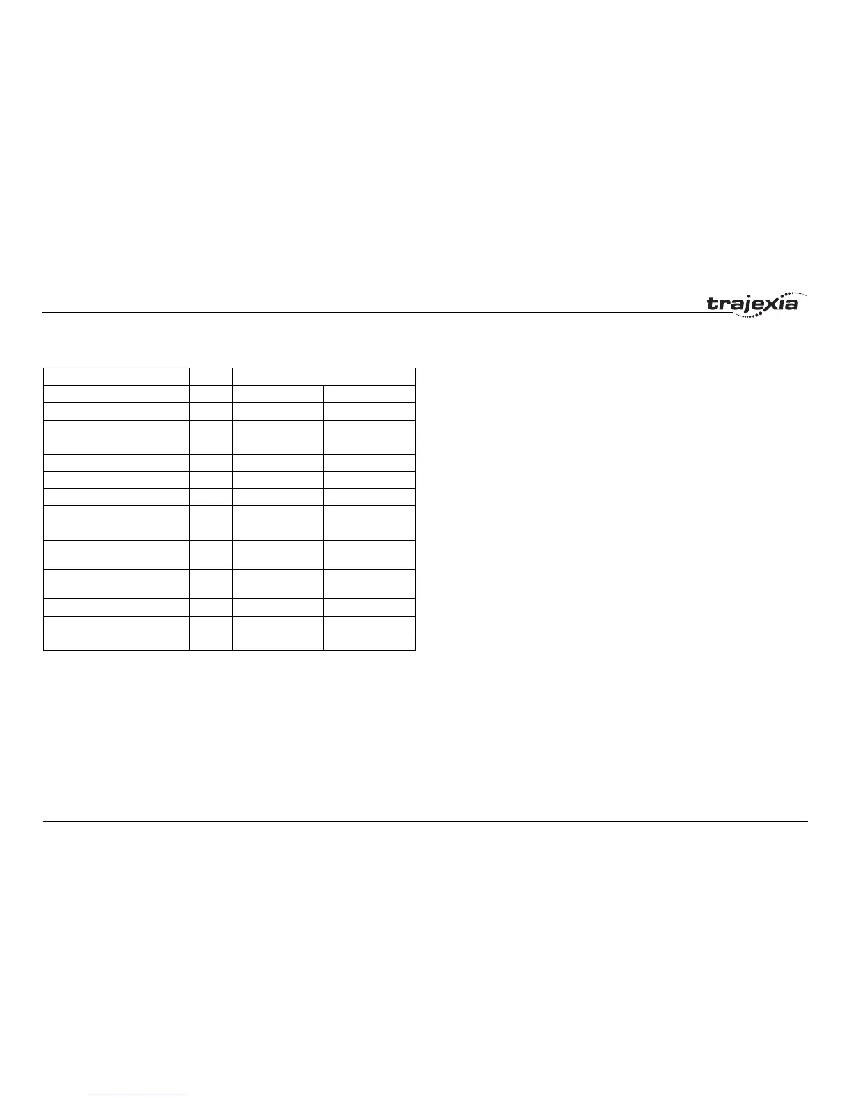
The table below lists the available functions which can be allocated to the
CN1 input signals.
/i
For more information on the CN1 I/O connector pins on the Servo Drivers,
refer to the specific Servo Driver manual.
Servo Driver inputs that are mapped into the Trajexia I/O space like this are
accessed within the program per axis and cannot be accessed in the usual
way with the IN command. The only way you can use these inputs in the
program is to assign them to the axis parameters DATUM_IN, FHOLD_IN,
FWD_IN and REV_IN. The inputs of the axis Servo Driver are used,
depending on the axis of which the parameters are set.
Signal name Symbol Set value
NO NC
Disabled --- 00h Setting not available
Forward drive prohibition input POT 01h 81h
Reverse drive prohibition input NOT 02h 82h
Emergency Stop Input STOP 14h 94h
External Latch Input 1 EXT1 20h Setting not available
External Latch Input 2 EXT2 21h Setting not available
Origin Proximity Input DEC 22h A2h
External Latch Input 3 EXT3 28h Setting not available
Forward External Torque
Limit Input
PCL 2Ch ACh
Reverse External Torque
Limit Input
NCL 2Dh ADh
Monitor Input 0 MON0 2Eh AEh
Monitor Input 1 MON1 2Fh AFh
Monitor Input 2 MON2 30h B0h