BASIC commands
PROGRAMMING MANUAL 86
Revision 1.0
3.2.94 DRIVE_CONTROL
/i
/i
/i
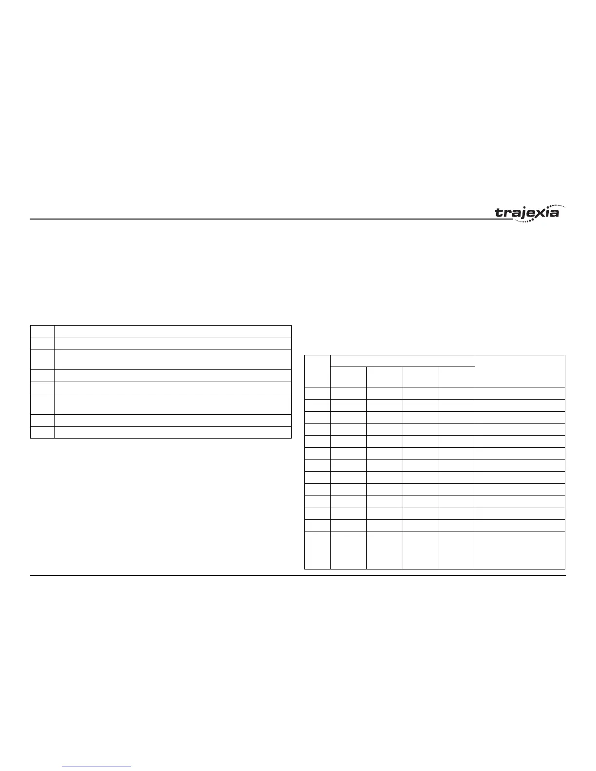
3.2.95 DRIVE_INPUTS
/i
/i
Type Axis parameter
Syntax DRIVE_CONTROL
Description When applied to an axis driven by the Servo Drive connected to the system
via the MECHATROLINK-II bus, this parameter selects the data to be moni-
tored by DRIVE_MONITOR according to the table below.
Code Description
2 Following error (this is the real FE when ATYPE=40 is used)
8 Feedback speed (With ATYPE=41 Units=Max Speed/40000000H, with other
ATYPE Units= reference units/s)
9 Command speed (units same as in Feedback Speed)
10 Target speed (units same as in Feedback Speed)
11 Torque (Force) reference (With ATYPE=42 Units=Max Torque/40000000H, with
other ATYPE Units= % over nominal Torque
14 Monitor selected with Pn813.0 Useful to monitor servo monitors (Unxxx)
15 Monitor selected with Pn813.1 Useful to monitor servo monitors (Unxxx)
When applied to an axis driven by the Servo Drive connected to the system
via the TJ1-FL02, this parameter sets outputs of the TJ1-FL02. Set bit 8 of
this parameter to switch on OUT 0 for an axis. Set bit 9 of this parameter to
switch on OUT 1 for an axis. Keep in mind that the same outputs are used by
the HW_PSWITCH command.
The command is executed on the Drive for the base axis set by BASE. The
base axis can be changed with the AXIS modifier, as with all the other axis
commands and parameters.
Arguments N/A
Example DRIVE_CONTROL AXIS(2) = 256
In this example, OUT 0 is switched on for axis 2, connected using the TJ1-
FL02.
See also N/A
Type Axis parameter
Syntax DRIVE_INPUTS
Description This parameter monitors the status of the inputs of the Servo Drive connected
via the MECHATROLINK-II bus. The parameter value is updated each
SERVO_PERIOD cycle. It is a bit-wise word with the bits as listed in the table
below.
Bit no. Servo Drive input signal Description
Sigma-II Sigma-V Junma G/G5-
series
0 P_OTP_OTP_OTP_OTForward limit switch
1 N_OTN_OTN_OTN_OTReverse limit switch
2 DEC DEC /DEC DEC Zero point return deceleration
3 PA PA Not used Not used Encoder A phase signal
4 PB PB Not used Not used Encoder B phase signal
5 PC PC Not used PC Encoder C phase signal
6 EXT1 EXT1 /EXT1 EXT1 First external latch signal
7 EXT2 EXT2 Not used EXT2 Second external latch signal
8 EXT3 EXT3 Not used EXT3 Third external latch signal
9 BRK BRK /BRK BRK Brake output
10 Reserved HBB E-STP E-STP Emergency stop switch
11 Reserved Reserved Not used SI2 General input 2
12 IO12 IO12 Not used PCL General input 12 (Sigma-II
and Sigma-V), Torque limit
input in positive direction (G/
G5)