EasyManuals Logo

Omron TM Series User Manual

Omron TM Series
80 pages
To Next Page IconTo Next Page
To Previous Page IconTo Previous Page
Page #30 background imageLoading...
Page #30 background image
Medium & Heavy Payload Series-Hardware Installation Manual TM12/14 Series Hardware Version: 3.2 30
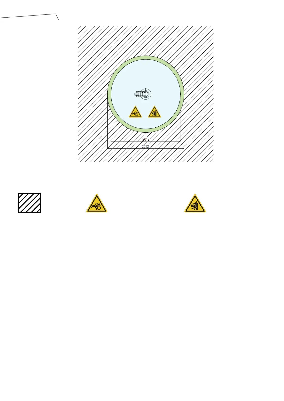
Figure 18: Top View of TM14 / TM14M / TM14X Movement Range Diagram
*All measures are in mm.
4.2.1.4 Robot Hazard Zone Diagram and Operator Position Diagram
Shown below is an illustration of the robot hazard zone and operator position diagrams. Do not operate
the robot while anyone is inside of the hazard zone to avoid safety risks.
Operator Position
Warning: Risk of crushing within
the operating area of the arm.
Warning: Risk of collision within
the operating area of the arm.

Table of Contents

Questions and Answers:

Question and Answer IconNeed help?

Do you have a question about the Omron TM Series and is the answer not in the manual?

Omron TM Series Specifications

General IconGeneral
TypeCollaborative Robot (Cobot)
Degrees of Freedom6
IP RatingIP54
Safety StandardsISO 10218-1, ISO/TS 15066
ModelTM Series
Power Supply100-240 VAC, 50/60 Hz
Operating Temperature0°C to 45°C
ProgrammingTMflow (Graphical Flowchart-based)
Communication InterfacesEthernet, USB
Vision SystemIntegrated Vision System (Camera in End Effector)
Payload4 kg to 14 kg (depending on model)
ControllerIntegrated controller

Related product manuals