Medium & Heavy Payload Series-Hardware Installation Manual TM12/14 Series Hardware Version: 3.2 32
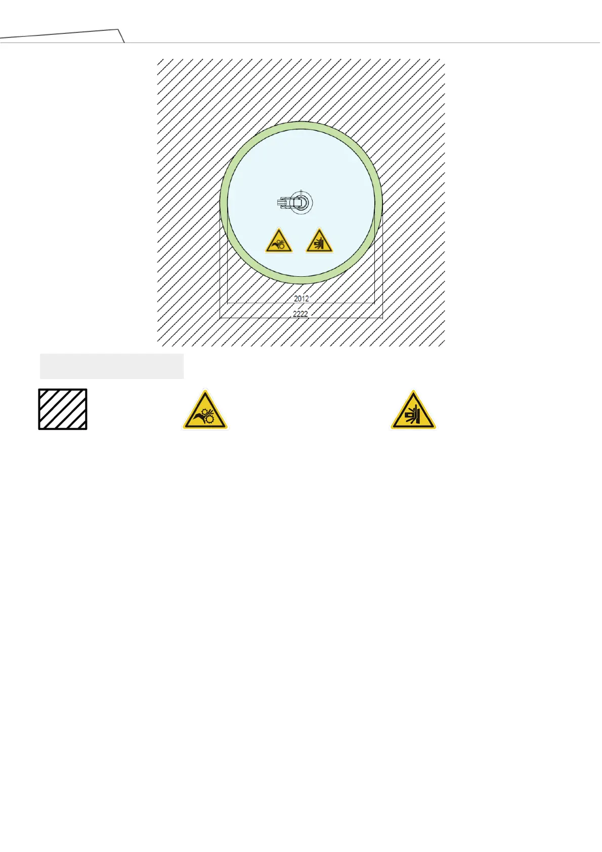
Figure 20: Robot Hazard Zone Diagram and Operator Position Diagram of TM14 / TM14M / TM14X
*All measures are in mm.
4.2.1.5 Payload and Torque
The maximum allowed payload of the robot arm is related to its center of gravity offset, which is defined
as the distance from the center point of tool flange to the payload’s center of gravity.
The following figure shows the relationship between payload and the center of gravity offset:
Warning: Risk of crushing within
the operating area of the arm.
Warning: Risk of collision within
the operating area of the arm.