5 Start Up
20 I67E-EN V1000 Quick Start Guide
Reference and Run Source
The drive has a LOCAL and a REMOTE mode. The LED in the LO/RE key indicates the
drive status.
If the drive is operated in the REMOTE mode, make sure that the correct sources for the fre-
quency reference and run command are set in parameters b1-01/02 and that the drive is in
the REMOTE mode.
I/O Setup
Multi-Function Digital Inputs (H1-)
The function of each digital input can be assigned in the H1- parameters. The default set-
ting functions can be seen in the connection diagram on page 9.
Multi-Function Digital Outputs (H2-)
The function of each digital output can be assigned in the H2- parameters. The default
setting functions can be seen in the connection diagram on page 9. The setting value of these
parameters consist of 3 digits, where the middle and right digit set the function and the left
digit sets the output characteristics (0: Output as selected; 1: Inverse output).
Multi-Function Analog Inputs (H3-)
The function of each analog input can be assigned in the H3- parameters. The default
setting of both inputs is “Frequency reference”. Input A1 is set for 0 to 10V input and A2 is
set for 4-20 mA input. The addition of both input values builds the frequency reference.
NOTICE! If the input signal level of input A2 is switched between voltage and
current, make sure that DIP switch S1 is in the correct position and
parameter H3-09 is set up correctly.
Monitor Output (H4-)
Use the H4- parameters to set up the output value of the analog monitor output and to
adjust the output voltage levels. The default monitor value setting is “Output frequency”.
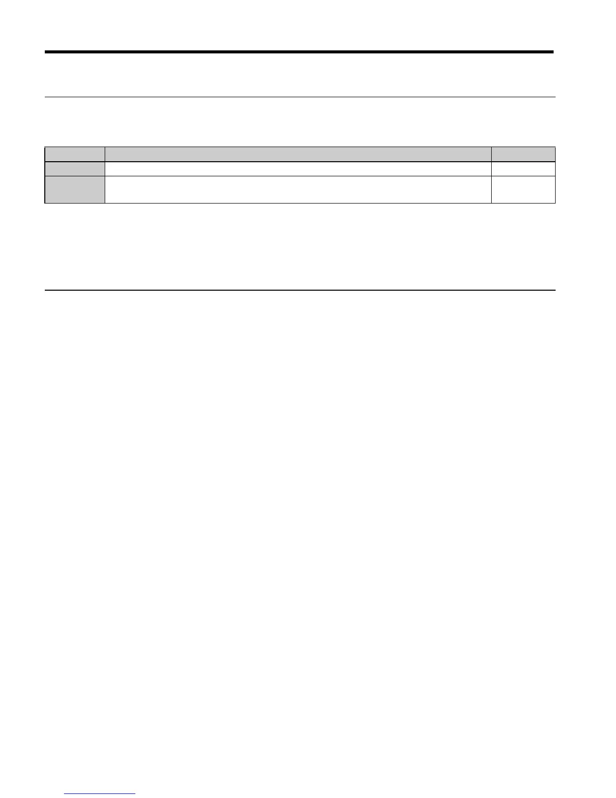
Status Description LO/RE LED
LOCAL The Run/ Stop command and the frequency reference are entered at the operator keypad. ON
REMOTE
The Run command source entered in parameter b1-02 and the frequency reference
source entered in parameter b1-02 are used.
OFF

 Loading...


