6 Parameter Table
I67E-EN V1000 Quick Start Guide 25
ENGLISH
L3-06
Stall Prev.
Level dur-
ing Run
Sets the current level at which stall
prevention during run starts to
operate.
Auto-Tuning
T1-01
Auto-Tun-
ing Mode
Selection
0:Rotational Auto-Tuning
2: Terminal resistance only
3: Rotational Auto-Tuning for
Energy Saving
T1-02
Rated
Power
Sets the motor rated power (kW).
T1-03
Rated
Vo l t a g e
Sets the motor rated voltage (V).
T1-04
Rated
Current
Sets the motor rated current (A).
T1-05
Base
Frequency
Sets the motor base frequency
(Hz).
T1-06 Motor Poles Sets the number of motor poles.
T1-07 Base Speed Sets the motor base speed (RPM).
T1-11
Motor Iron
Loss
Iron loss for determining the
Energy Saving coefficient.
If unknown leave it on default.
Monitor Description
U1-01 Frequency Reference (Hz)
U1-02 Output Frequency (Hz)
U1-03 Output Current (A)
U1-05 Motor Speed (Hz)
U1-06 Output Voltage Reference (Vac)
U1-07 DC Bus Voltage (Vdc)
U1-08 Output Power (kW)
U1-09 Torque Reference (% of motor rated torque)
Par. Name Description
U1-10
Input Terminal Status
U1-11
Output Terminal Status
U1-12
Drive Status
U1-13 Terminal A1 input level
U1-14 Terminal A2 input level
U1-16
Soft Starter Output (fref after accel./decel.
ramps)
U1-18 OPE Fault Parameter
U1-24 Pulse Input frequency
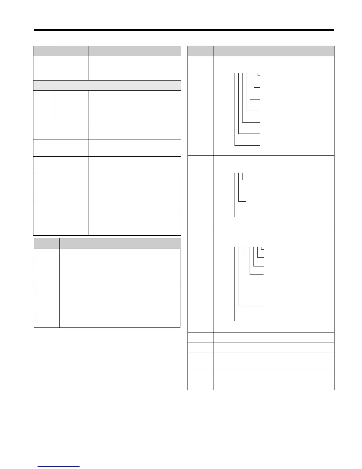
Monitor Description
U1-10
=
0000000
1: Digital input 1
(terminal S1 enabled)
1: Digital Input 2
(terminal S2 enabled)
1: Digital Input 3
(terminal S3 enabled)
1: Digital Input 4
(terminal S4 enabled)
1: Digital Input 5
(terminal S5 enabled)
1: Digital Input 6
(terminal S6 enabled)
. . .
U1-11
=
000
1: Relay Output
(terminal MA-MC closed
MB-MC open)
1: Open Collector Output 1
(terminal P1) enabled
1: Open collector Output 2
(terminal P2) enabled
U1-12
=
00000000
1: During run
1: During zero-speed
1: During REV
1: During fault reset
signal input
1: During speed agree
1: Drive ready
1: During alarm
detection
1: During fault
detection

 Loading...


