4-5SectionOperation Test (TEST)
69
If the start address is set, only the data in that location is displayed.
While
the read test is in progress, the data in the display flashes every second,
and
the ID
Controller head number display indicator also flashes every second.
Note When
an error occurs in communications between the DC and a R/W
Head,
the error code is displayed (see
page
97). When this happens,
use the horizontal cursor keys to display the error message.
Note If the address setting is incorrect (start address > End address), then only the
contents of the start address location are read.
4-5-2 Test Write
One
byte of data is written to the specified DC address (or locations from start
address to end address) repeatedly.
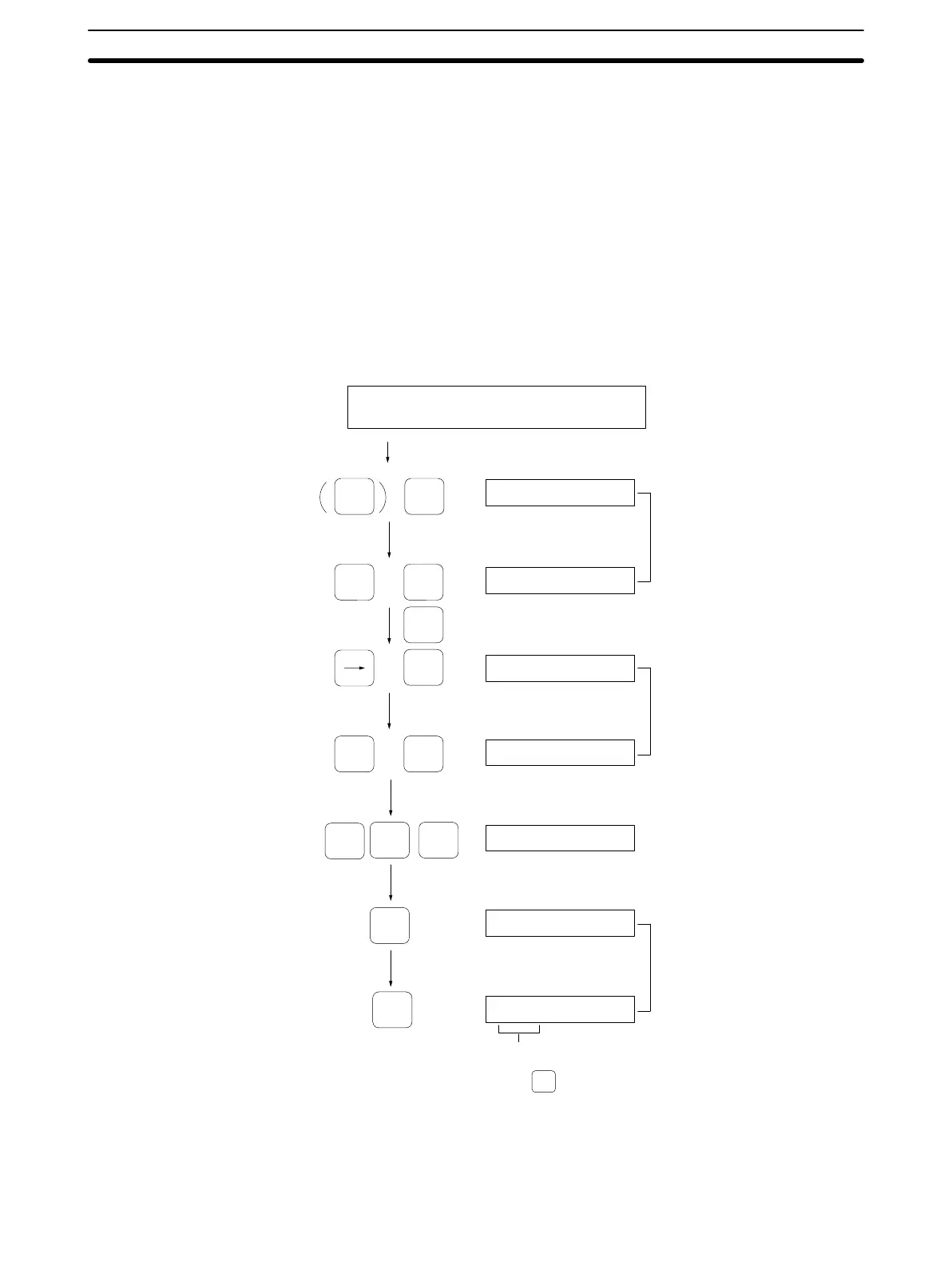
Operation Procedure This example shows the procedure for writing 5A into locations 10 to 1F.
a1FdXX
2
a
_
dXX
RESET ARDS
Job
specification
(Head no. and Page no)
1 0
a
_
dXX
a10dXX
a10d5A
1 F
DATA
5 A
TEST 14
TEST
TWT d5A
(2)
(1)
(3)
(4)
ADRS
ADRS
Test write display
RESET
(Cancel
operation by pressing )
(5)
1, 2, 3...
1. Specify the address(es) to which data is to be written.
Note In the case of a SRAM DC, data cannot be written to addresses 00
and 01 on Page 0. In this example, data is written to address 10.

 Loading...


