36
SECTION 2
Connection and Wiring
RFID System
User’s Manual
SECTION 2
Installation, Connections, and Wiring
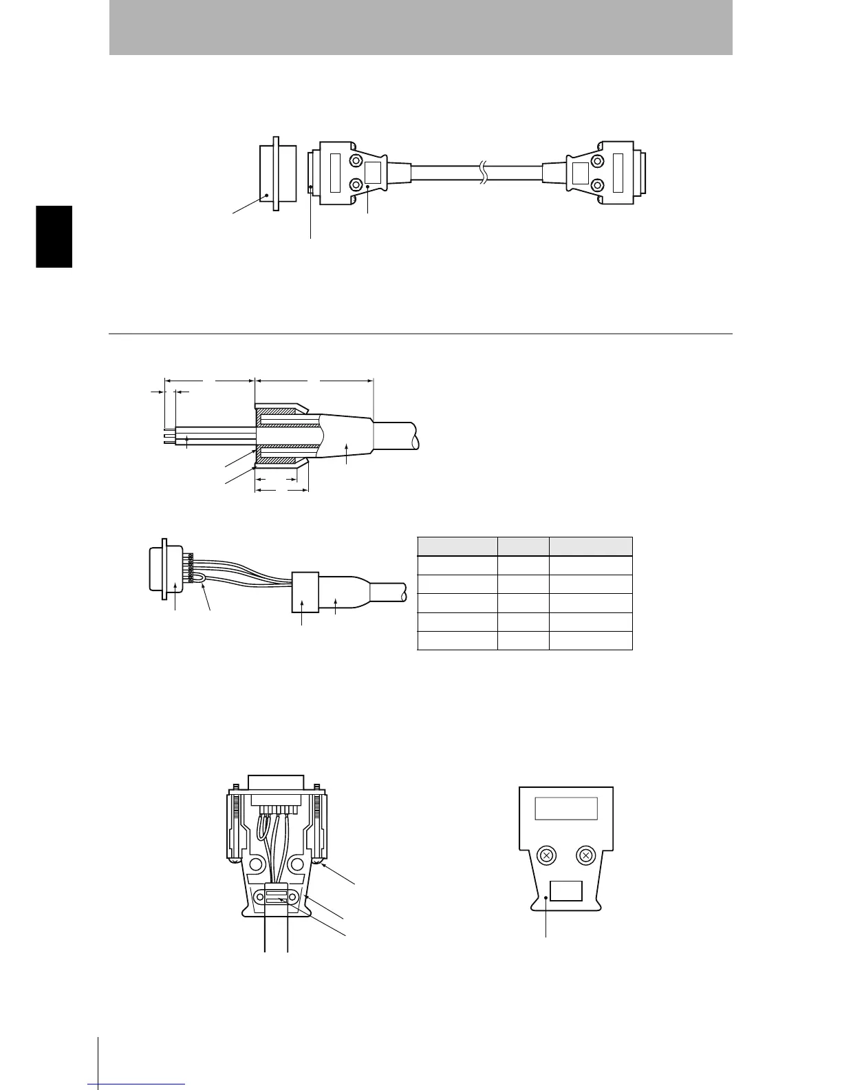
Assembling and Connecting the Communications Connector
Have a connection cable and connector ready.
Assembling the Connector
1. Prepare the end of the cable as shown below.
• Insert the cable into the cable bushing.
• Unravel the braided shield for approximately 10 mm and fold it
back on the cable bushing.
• Apply shield tape to the folded braided shield.
2. Solder the conductors to the plug pins.
3. Attach housing A2 of the Hood to the Plug and secure the aluminum-taped portion with the cable
clamp.
4. Secure the two connector lock screws and put on housing B2 to complete the connector.
Controller end
OMRON
XM3B-0922-111
Plug
OMRON
XM2S-0911
Hood
Host device end
OMRON
XM2A-0901
Plug
40
35
5
Conductors
Braided shield
Shield tape
10±1
12
Cable bushing
Pin No. Symbol Signal name
9 SG Signal ground
2 SD Send data
3 RD Receive data
4 (See note.) RS Request to send
5 (See note.) CS Clear to send
Note: Short-circuit pins 4 (RS) and 5 (CS) with a jumper.
Plug Jumper
Aluminum
tape
Cable bushing
Two, M2.6 lock screws
Housing A2
Cable clamp
Housing B2