120
SECTION 7
Characteristics According to Operating Conditions
RFID System
User's Manual
SECTION 7
Appendices
Characteristics According to Operating Conditions
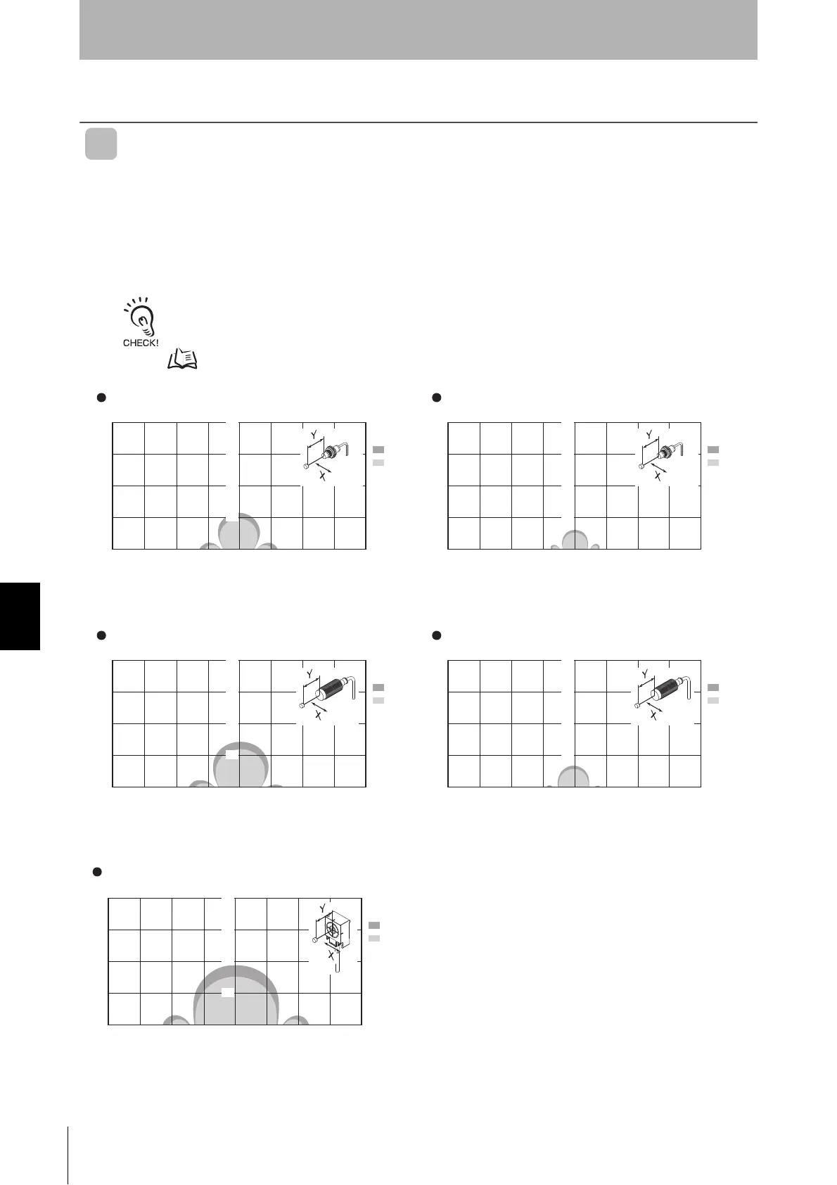
Interrogation Zone (Reference)
The following diagram shows the interrogation zone for the V680 Series. The interrogation zone
depends on the installation conditions and environmental conditions.
The following diagram shows the interrogation zone when a RF Tag passes by and perpendicular to
the center of the Antenna. The Antenna and RF Tag surfaces are parallel to each other.
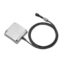
V680-D1KP52MT
The interrogation zone given here are for reference only. For information on communications ranges, refer to
Communications Range Specifications in this section. The interrogation zone depends on the type of RF Tags used, the
ambient temperature, surrounding metals, and noise. Be sure to check carefully when installing the system.
p.103
20
30
10
Y
-40 -30 -20 -10 10 20 30 X0
Read
Write
(Embedded in Metal: Steel)
20
30
10
Y
-40 -30 -20 -10 10 20 30 X0
20
30
10
Y
-40 -30 -20 -10 10 20 30 X0
20
30
10
Y
-40 -30 -20 -10 10 20 30 X0
20
30
10
Y
-40 -30 -20 -10 10 20 30 X0
V680-HS51䋨Embedded in Metal䋩 and V680-D1KP52MT V680-HS51䋨Embedded in Metal䋩 and V680-D1KP52MT
(Embedded in Metal: Steel)
V680-HS52䋨Embedded in Non-Metal䋩 and V680-D1KP52MT V680-HS52䋨Embedded in Non-Metal䋩 and V680-D1KP52MT
V680-HS63䋨with Non-Metal on Back Surface䋩 and V680-D1KP52MT
Read
Write
Read
Write
Read
Write
Read
Write