RFID System
User's Manual
(Modbus TCP)
Section 3 Component Names
Section 3
Component Names
65
Operation Indicators
RUN
RF
NORM/ERR
The NORM/ERR indicator shows the result of communications with an RF Tag.
LINK/ACT
Refer to Errors and Indicator Status in Section 9 Troubleshooting for information of Error content of the operation indicator
p.243
Connector
The connector is used to connect the exclusive cable as model V680S-40 @M, V680S-A41 @M,
V680S-A42 @M, V680S-A50 @M, or V680S-A51 @M.
Status Meaning
green Lighting while the Reader/Writer is operating normally.
Flashing
green
Flash while the Reader/Writer is operating in Safe mode.
Flashing
green
quickly
Flashes quickly during Reader/Writer initialization. (Flashes at 200-ms intervals.)
yellow Lights yellow while the Reader/Writer is operating in Slave Mode.
Not lit Turn off when power is not supplied.
Status Meaning
yellow Lighting during communication for RF Tag.
Not lit Turn off when not in communication with no error.
Status Meaning
green Lighting when the communications finish with no error.
When communication diagnostic is enabled, this indicator will flash once each time a stable communication is detected.
yellow When communication diagnostic is enabled, this indicator will flash once each time an unstable communication is detected.
red Lighting once when an error occurs during communications with the host device, or during communications with an RF Tag.
Lighting when unrecoverable error occurs.
Flashing
red
Flash when recoverable error occurs. (Configuration memory error, or Control signal wiring mistake, etc.)
Flashing
red
irregularly
Flashes red irregularly when the same IP address is detected for two different devices on the network at startup. (It will
repeatedly flash twice for 100 ms at 1-s intervals.)
Not lit Turn off when the standby state.
Status Meaning
green Lighting during linking normaly.
Flashing
green
Flash during detects a carrier.
Not lit Turn off when the ethernet cable is not connected.
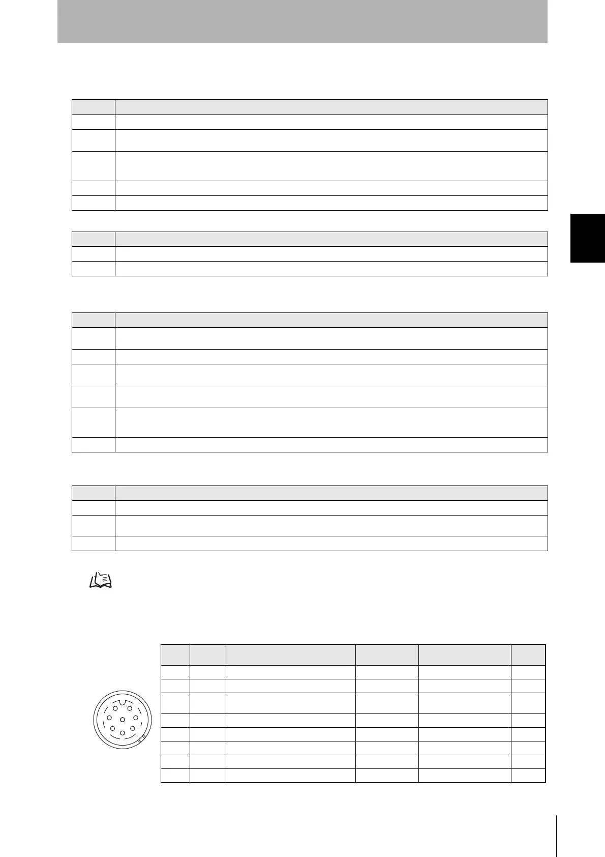
Pin
No.
Name Description
V680S-A41/-A51
wire color
V680S-A42 wire color I/O
1 24P +24V Brown Brown ---
2 FG Frame ground --- (Drain wire) ---
3CONT
Control signal
(Controls entering Safe Mode.)
Violet Violet Input
4 TD- Ethernet send - signal --- Orange Output
5 RD+ Ethernet receive + signal --- Green with white strip Input
6 TD+ Ethernet send + signal --- Orange with white strip Output
7 24N 0V Blue Blue ---
8 RD- Ethernet receive - signal --- green Input
1
2
3
4
5
6
7
8

 Loading...