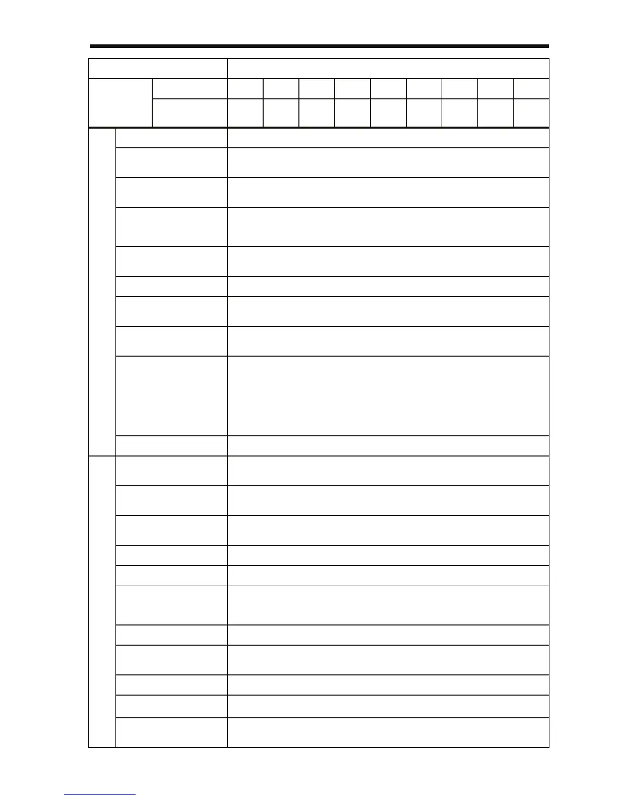
9 Specifications
219
Control Method Sine wave PWM (V/f control/vector control selectable)
Frequency Control
Range
0.1 to 400 Hz
Frequency Accuracy
(Temperature Change)
Digital reference: ±0.01 %, −10 to 50 °C (14 to 122 °F)
Analog reference: ±0.5 %, 25±10 °C (59 to 95 °F)
Frequency Setting
Resolution
Digital reference:
0.01 Hz (less than 100 Hz)/0.1 Hz (100 Hz or more)
Analog reference: 1/1000 of max. output frequency
Output Frequency
Resolution
0.01 Hz
Overload Capacity 150% rated output current for one minute
Frequency Reference
Signal
0 to 10 VDC (20 kΩ), 4 to 20 mA (250 Ω), 0 to 20 mA (250 Ω) pulse train
input, frequency setting potentiometer (Selectable)
Acceleration/Decelera-
tion Time
0.00 to 6000 s
(Acceleration/deceleration time are independently programmed.)
Braking Torque
Short-term average deceleration torque
*2
0.2 kW: 150% or more
0.75 kW: 100% or more
1.5 kW (2 HP): 50% or more
2.2 kW (3 HP) or more: 20% or more
Continuous regenerative torque: Approx. 20% (150% with optional brak-
ing resistor, braking transistor built-in)
V/f Characteristics Possible to program any V/f pattern
Motor Overload
Protection
Electronic thermal overload relay
Instantaneous Over-
current
Motor coasts to a stop at approx. 250% or more of Inverter rated current
Overload Motor coasts to a stop after 1 minute at 150% of Inverter rated output cur-
rent
Overvoltage Motor coasts to a stop if DC bus voltage exceeds 820 V
Undervoltage Stops when DC bus voltage is approx. 400 V or less
Momentary Power
Loss
The following items are selectable: Not provided (stops if power loss is 15
ms or longer), continuous operation if power loss is approx. 0.5 s or short-
er, continuous operation.
Heatsink Overheat Protected by electronic circuit.
Stall Prevention Level Can be set to individual levels during acceleration/constant-speed opera-
tion, provided/not provided available during deceleration.
Cooling Fan Fault Protected by electronic circuit (fan lock detection).
Ground Fault
*4
Protected by electronic circuit (overcurrent level).
*3
Power Charge
Indication
ON until the DC bus voltage becomes 50 V or less. Charge LED is pro-
vided.
Voltage Class 400 V 3-phase
Model
CIMR-
V7AZ
3-phase 40P2 40P4 40P7 41P5 42P2 43P0 44P0 45P5 47P5
Single-phase---------
Control CharacteristicsProtective Functions