6 Programming Features
97
1. Reduce the continuous output current when changing the
carrier frequency to 4 (10 kHz) for 200 V Class (1.5 kW
or more) and 400 V Class Inverters. Refer to the table
above for the reduced current.
Operation Condition
• Input power supply voltage:
3-phase 200 to 230 V (200 V Class)
Single-phase 200 to 240 V (200 V Class)
3-phase 380 to 460 V (400 V Class)
• Ambient temperature:
−10 to 50°C (14 to 122°F)
(Protection structure: open chassis type IP20,
IP00)
−10 to 40°C (14 to 105°F)
(Protection structure: enclosed wall-mounted
type NEMA 1 (TYPE 1))
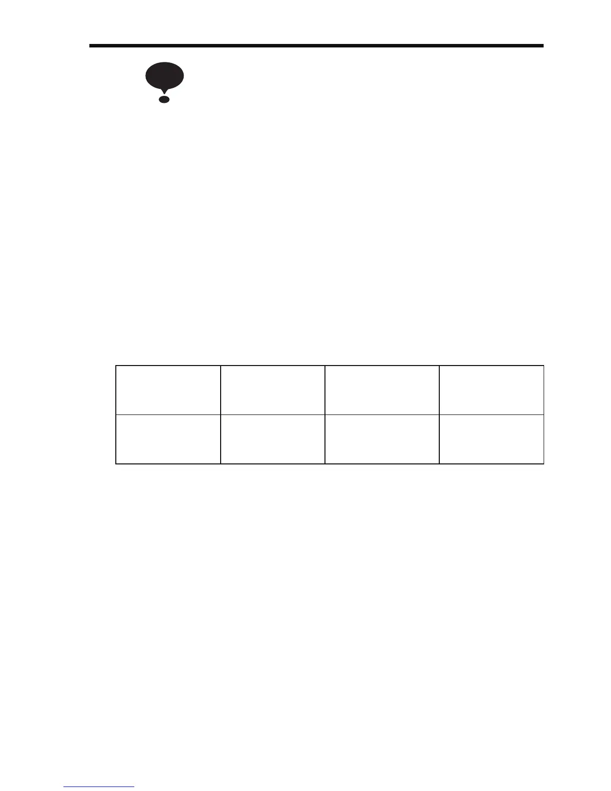
2. If the wiring distance is long, reduce the Inverter carrier
frequency as described below.
3. Set the Carrier Frequency Selection (n080) to 1, 2, 3, or 4
when using vector control mode. Do not set it to 7, 8, or 9.
4. If the Inverter repeatedly stops and starts with a load
exceeding 120% of the Inverter rated current within a
cycle time of 10 minutes or less, reduce carrier frequency
at a low speed. (Set constant n175 to 1.)
5. The carrier frequency is automatically reduced to 2.5 kHz
when the Reducing Carrier Frequency Selection at Low
Speed (n175) is set to 1 and the following conditions are
satisfied:
Output frequency ≤ 5 Hz
Output current ≥ 110%
Factory setting: 0 (Disabled)
Wiring Distance
between Inverter
and Motor
Up to 50 m Up to 100 m More than 100 m
Carrier Fre-
quency (n080
setting)
10 kHz or less
(n080=1, 2, 3, 4,
7, 8, 9)
5 kHz or less
(n080=1, 2, 7, 8, 9)
2.5 kHz or less
(n080=1, 7, 8, 9)
NOTE