EasyManua.ls Logo

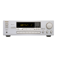
Onkyo TX-8511

Onkyo TX-8511
28 pages
To Next Page IconTo Next Page
To Previous Page IconTo Previous Page
Loading...
Precautions
Supplied
accessories
1.
Warranty
Claim
You
can
find
the
serial
number
on
the
rear
panel,
bi
case
ol'
war-
ranly
claim,
please
report
this
number.
2.
Recording
Copyright
Recording
of
copyrighted
material
for
other
than
personal
u.se
is
illegal
without
permission
of
the
copyright
holder.
3.
AC
Fuse
The
fuse
is
located
inside
the
cha.ssis
and
is
not
user-serviceable.
If
power
does
not
come
on.
contact
your
Onkyo
authorized
service
station.
4.
Care
From
time
to
time
you
should
wipe
the
front
anil
rear
panels
and
the
cabinet
with
a
soft
cloth.
For
heavier
dirt,
dampen
a
.soft
cloth
in
a
weak
solution
of
mild
detergent
and
water,
wring
it
out
dry,
and
wipe
off
the
dirt.
Following
this,
dry
immediately
with
a
clean
cloth.
Do
not
use
rough
material,.thinners,
alcohol
or
other
chemi¬
cal
solvents
or
cloths
since
these
could
damage
the
finish
or
remove
the
panel
lettering.
5.
Power
WARNING
BEFORE
PLUGGING
IN
THE
UNIT
FOR
THE
FIRST
TIME.
READ
THE
FOLLOWING
SECTION
CAREFULLY.
Some
models
are
designed
for
use
only
with
the
power
supply
voltage
of
the
region
where
they
are
sold.
European
and
Australian
inodeIs:AC
230V,
50H/.
U.S.
and
Canadian
models:
AC
120V,
60H/,
Worldwide
model:
AC
220-230V/I20V
swiichable.
50/60H7.
Other:
AC
220V.
601
Iz
Vuitage
Selector
(Rear
I’anel)
Worldwide
models
are
ei|uipped
with
a
voltage
.selector
to
con¬
form
to
local
power
supplie.s.
Be
sure
to
set
this
.switch
to
match
the
voltage
of
the
power
supply
in
your
tirea
before
plugging
in
the
unit.
(See
below.)
Models
without
a
voltage
.selector
can
only
be
u.scd
in
areas
where
the
power
supply
is
the
same
as
that
of
the
unit.
The
jtower
does
not
shut
off
completely
by
just
turning
the
power
off.
So
power
cord
should
be
removed
from
AC
outlet
when
not
in
use
fora
prolonged
time.
Before
operating
this
Remote
control
RC-329S
(1)
Battery
(size
AA.
R6,
or
UM-3)
(2)
AM
loop
antenna
(1)
T-shaped
FM
antenna
(1)
unit
Setting
the
voltage
selector
(worldwide
mod^^n
ly)
1.
Determine
the
proper
voittige
for
your
area:
220-230
V
or
120
V.
2,
If
,the
.setting
on
the
voltage
.selector
is
not
correct,
insert
a
screwdriver
into
the
groove
in
the
switch
and
slide
the
switch
completely
to
the
right
(120
V)
or
the
left
(220
-
230
V),
whichever
is
appropriate.
Setting
the
tuning
step
fre-
;
quency
(worldwide
model
only)
The
worldwide
model
is
eijuipped
with
a
switch
that
controls
the
AM
(9
kHz/
10
kHz)
band
tuning
steps.
Please
.set
this
switch
to
match
the
tuning
step
frequency
in
your
area.
U.S.
&
Canada:
USA
Other
areas:
OTHER

Related product manuals