Do you have a question about the Onkyo TX-RZ830 and is the answer not in the manual?
Conform to product regulations and maintain a safe servicing environment by following safety instructions.
To keep original performance, perform optimum adjustments and characteristic confirmations.
Use specified grease and adhesives, ensuring the proper amount is applied.
Perform proper cleaning for parts like optical pickups and tape heads to restore performance.
Components marked with a symbol are critical for fire and shock risk; replace with specified ONKYO parts.
Check that all removed parts and wires are correctly reinstalled and structural integrity is maintained.
Danger of explosion if batteries are replaced incorrectly; use same or equivalent type.
Cautions regarding AC plug polarity, lead-free solder, laser radiation, and proper soldering techniques.
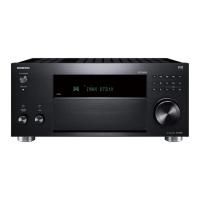
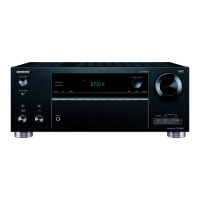
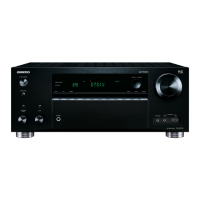
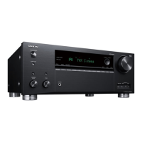
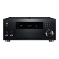
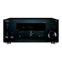
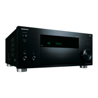
Diagram showing the front panel layout of the TX-RZ830 AV Receiver.
Diagram showing the rear panel layout with all connections and ports.
Illustration of the remote control unit with its buttons.
List of included accessories such as remote controller, batteries, microphone, and antennas.
Procedure to save user preferences using SETUP and ENTER buttons.
Procedure to reset the unit by pressing specific buttons and unplugging the power cord.
Procedure to load user preferences using SETUP and RETURN buttons.
The unit enters standby automatically upon detecting abnormal conditions like thermal or voltage issues.
Function to avoid capacitor rupture by checking amplifier circuits for faults during power-on.
Steps to confirm protect causes, clear NG CH information, and cancel self-diagnostics.
How to manually initiate the self-diagnostic function via button combinations.
How to enter service mode, display service information, and clear protect data.
Pressing any input selector button to exit service mode.
Procedure to select 'ProtectDataCLR' and press ENTER to clear protect data.
Listening Mode Code List for identifying various audio modes.
Importance of setting the appropriate country code for the 5GHz band due to radio laws.
Default country code is set on the PRC board; ensure it matches customer's country.
Ensuring the country code on the PRC board matches the customer's country code.
List of country codes for America, Asia/Oceania, and Middle East regions.
List of country codes for Europe/Africa regions.
Explanation of how to interpret PRC board part numbers for destination and default country code.
Steps to check firmware versions and prepare for updates by downloading files.
Connecting USB storage, turning on unit, and pressing buttons to access firmware update menu.
Explains the possibility of overwriting existing firmware with new versions.
Steps for starting firmware update, waiting for completion, and checking the new version.
Table showing model names, destinations (codes), and FL display examples.
Procedure to check idling current before aging, including terminals and resistance values.
The AVR is turned on for about 6 minutes for aging process.
Procedure to check idling current after aging, including resistance values.
Troubleshooting steps for no sound from connected players, TV, or loudspeakers.
Troubleshooting steps for no picture from connected players via HDMI or component video terminals.
Troubleshooting steps for no power condition or front panel indication issues.
Troubleshooting table for no sound issues specifically related to HDMI input.
Troubleshooting table for no sound issues related to optical input.
Troubleshooting table for no sound issues related to analog inputs.
Troubleshooting table for no picture issues related to HDMI connections.
Troubleshooting table for no picture issues with component input or HDMI output.
Troubleshooting table for no picture issues with composite input or HDMI output.
Troubleshooting table for no power issues, including checks for remote control and main unit operation.
Detailed check points and voltage references for the BAPRC-2605 PCB.
Detailed check points and voltage references for the BADG-2586 PCB.
Troubleshooting for BAAF-2597 and BACLA-2587 PCBs, including damage checks.
Troubleshooting for the BAPS-2585 PCB, including AC rated voltage checks.
Visual inspection for damage on ANY PARTS on BAAF-2597 PCB.
Checking damage and connection for the P7001 FFC, which is part of the BADIS-2575 PCB.
Block diagram illustrating the analog audio signal path and components.
Block diagram illustrating the video signal path and related components.
Block diagram illustrating the digital audio signal processing and connections.
Detailed schematic of the Amplifier Signal Processing (ASP) section.
Detailed schematic of the Amplifier section, showing output stages for different channels.
Schematic of the Power Supply (PS) section, including switching power supply and transformer.
Schematic for video processing, speaker output, IR receiver, and 12V trigger.
Schematic illustrating the output for Zone 2 powered speakers.
Schematic for the RS-232C communication interface.
Schematic for the front panel display and related controls like keys and volume.
Schematic for the headphone jack and related circuitry.
Schematic for the switch section, showing connections for various input sources and display.
Schematic for the display and setup buttons, showing their connections.
Schematic for the display and selector buttons, showing connections for input sources.
Schematic for the volume control display and related components.
Schematic for the display and encoder controls, including listening mode and tone.
Schematic for the microphone input and related circuitry.
Schematic for the switch section, showing connections for various input sources and the hybrid standby LED.
Schematic for microphone input and headphone jack, including connections to TRM.
Schematic for digital inputs, VLSC, and Low-Pass Filter sections.
Schematic of the Main Microprocessor Unit (MPU) section, including REPROM and DSP connections.
Schematic of the Vector Processing Unit (VMPU) section, showing connections to HDMI and other interfaces.
Schematic of the Video Signal Processing (VSP) section, detailing HDMI inputs and processor connections.
Schematic of the HDMI receiver and decoder section, showing connections to various HDMI inputs.
Schematic of the Digital Input Receiver (DIR) and Digital-to-Analog Converter (DAC) sections.
Schematic of the first Digital Signal Processor (DSP) section, showing connections to MMPU and NET.
Schematic of the second Digital Signal Processor (DSP) section, detailing connections to MMPU and NET.
Schematic detailing the ARM Input/Output section, including connections to USB, Ethernet, and WiFi.
Schematic of the ARM Power Supply (PS) section, showing voltage regulation and control.
Schematic of the ARM section for USB, Ethernet, and WiFi modules and their connections.
Schematic of the power supply section, illustrating various voltage regulators and power distribution.
Schematic of the tuner section, showing connections to the FM/AM tuner module.
Schematic of the front HDMI input section, including connections to the HDMI transceiver and I2C bus repeater.
Schematic of the HDBaseT section, including connections to Sil9396 and Sil9630 chips.
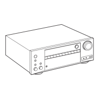
Exploded view illustrating the packing of the TX-RZ830 unit and its accessories.
Exploded view of the TX-RZ830, highlighting the WiFi/Bluetooth module and regulatory information.
Exploded view showing the front panel components and their assembly.
Exploded view showing the front panel components and their assembly, referring to Front Section 3.
Exploded view showing the internal front section components and their assembly.
Exploded view showing the rear panel components and their assembly, including PCBs and power transformer.
Exploded view highlighting the MMR (Model/Manufacturer) information on the rear panel.
Illustration showing the application of FLOIL to a specific component with a brush.
Explanation of expressions used to simplify button operation descriptions, with examples.
Procedures for STORE, RESET, and RECALL functions to manage user preferences.
How to display and verify the main MCU checksum, especially after firmware updates.
Procedure to test if each key/button is functioning normally, displaying key names on the FL tube.
Procedure to confirm all LEDs and FL tube segments are lit, and to perform a clear reset.
Step-by-step instructions on entering the service mode via button combinations.
Instructions on how to exit the service mode by pressing any input selector button.
Procedure to select 'ProtectDataCLR' and press ENTER to clear protect data.
Flowchart for navigating the service mode, covering Tech Sprt, Audio, and Video sections.
Flowchart for navigating the service mode, covering Video, Sales, and Other sections.
Explanation of Main Checksum, Protect Data, ProtectDataCLR, HardwareStatus, AmpChDiag, and Model Check.
Explanation of FAD Mode, DOLBY VDB Thru, HDMI Thru, Power Control, TV Control, and Max TMDSCR settings.
Explanation of LTE 340 SC, Thru Sel Change, Pass thru MD, Content Type, HDBaseT Update, and HDBaseT Reset.
Explanation of Photo mode for sample display during photography.
List of cabinet, chassis, screws, and nuts parts.
List of semi-conductor components like diodes and transistors.
List of transformer and coil components.
List of accessories including remote control, batteries, and antennas.
List of chip type ceramic capacitors and UTSP type electrolytic capacitors.
List of chip type carbon resistors.
List of switch, terminal, and wire components.
| Impedance | 16 Ω |
|---|---|
| Receiver type | Surround |
| Frequency range | 5 - 100000 Hz |
| Pre-out channels | 11.2 |
| Input sensitivity | 200 mV |
| Pre-out connectivity | Yes |
| Audio output channels | 9.2 channels |
| Signal-to-Noise Ratio (SNR) | 106 dB |
| Total Harmonic Distortion (THD) | 1 % |
| Dynamic power per channel (3 Ohm) | 250 W |
| Dynamic power per channel (4 Ohm) | 220 W |
| Dynamic power per channel (8 Ohm) | 130 W |
| Power output per channel (20-20KHz@8 Ohm) | - W |
| HDMI in | 7 |
| Digital audio coaxial in | 1 |
| Component video (YPbPr/YCbCr) in | 2 |
| Headphone connectivity | 6.3 mm |
| Number of HDMI outputs | 3 |
| Connectivity technology | Wired & Wireless |
| Speakers connectivity type | 3.5mm |
| Audio formats supported | AIFF, ALAC, FLAC, WAV, WAVE |
| Ethernet LAN | No |
| Bluetooth version | 4.1 |
| Bluetooth profiles | A2DP, AVRCP |
| AM band range | 522 - 1710 kHz |
| FM band range | 87.5 - 108 MHz |
| Supported radio bands | AM, FM |
| Preset stations quantity | 40 |
| Internet radio services supported | Amazon Music, Deezer, Spotify, Tidal, TuneIn |
| Supported video modes | 480i, 480p |
| Display | - |
| Product color | Silver |
| Audio decoders | DSD, DTS-HD Master Audio, DTS-HD Master Audio 5.1, DTS:X, Dolby Atmos, Dolby TrueHD |
| Cables included | AC |
| Package weight | 17000 g |
| THX-certified | THX Select |
| AC input voltage | 220-240 V |
| AC input frequency | 50 - 60 Hz |
| Power consumption (standby) | 0.15 W |
| Power consumption (typical) | 850 W |
| Depth | 398 mm |
|---|---|
| Width | 435 mm |
| Height | 201.5 mm |
| Weight | 14000 g |