NLV-4001
2nd
5
Electrical specifications
5
<Configuration>
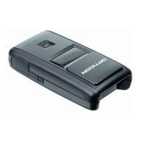
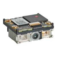
The scanner consists of
- CCD Module section; where the 1500-pixel CCD sensor, illumination LED, light receiving lens and
illumination lens are mounted, and
- Main PCB; where the CPU (decode/communication controller which processes bar code signals are
combined), the power supply section that converts the main power to 3.3 V, the communication
interface section to output the decoded data, the indicators (buzzer / status LED)
The USB interface models are bus powered so no external power supply is needed, while the RS-
232C interface model needs a DC 4.5-5.5V power supply.
For the RS-232C model, make sure that the host device is powered off when connecting to the host
device and inserting.
Figure 2: Configuration Diagram
5.1 USB Specification
Bus-Power Class : 500 mA max (Hi-Power)
Current consumption* : 50 mA (Typ.) in stand-by mode
: 180 mA (Typ.) during reading operation
* The current consumption was measured at 25°C.
* The current consumption may vary depend by the connected host device.
5.2 RS-232C Specification
Input power supply voltage : DC 5.0 V
Range of working voltage : 4.5 - 5.5 V
Maximum current : 0.5 A (max)
Current consumption* : 50 mA in stand-by mode
: 180 mA (typ) during reading operation
* The current consumption was measured at 25°C.
* The current consumption may vary depend by the connected host device.
Illumina-
tion
LED
Imaging
Lens
CCD
Illumination
Red LED
CPU+
FROM/SDRAM
Buzzer
Status
LED
I/F
(RS-232C/USB)
3.3 V ← +4.5-5.5 V
Power
Supply
Section
Interface Section
Host
Host
Camera Module & Decoder Section
Communication Control Section
+4.5–5.5 V
FPC
 Loading...