OPTIMUM
MASCHINEN - GERMANY
Unpacking and connecting
Version 1.1.5 dated 2015-08-31 Page 23Original operating instructions
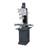
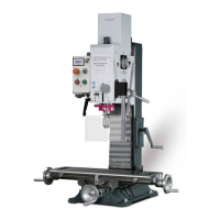
BF30Vario GB
Any parts sticking out such as stops, handles, etc. have to be secured by measures taken
by the customer if necessary in order to avoid endangerment of persons.
Provide sufficient space for the staff preparing and operating the machine and transporting
the material.
Also consider that the machine is accessible for setting and maintenance works.
Provide for sufficient illumination (Minimum value: 500 lux, measured at the tool tip). At little
intensity of illumination an additional illumination has to be ensured e.g. by means of a sepa-
rate workplace lamp.
INFORMATION
The mains plug of the drilling-milling machine must be freely accessible.
3.4.2 Load suspension point
WARNING!
Danger of crushing and overturning. Proceed carefully when lifting, installing and assembling
the machine.
Secure the load-suspension device around the drill-mill head. Use a lifting sling for this pur-
pose.
lifting sling.
Firmly clamp all clamping levers on the drilling-milling machine before lifting the drilling-mill-
ing machine.
Make sure that the load attachment does not cause damage to components or paint.
3.4.3 Assembly
Check if the underground of the drilling-milling machine is level using a spirit level.
Check if the underground is sufficiently stable and rigid. The total weight amounts to 265 kg.
ATTENTION!
Insufficient rigidity of the foundation leads to the superposition of
vibrations between the drilling-milling machine and the foundation (natural frequency of
components). Critical speeds and moves in the axis with displeasing vibrations are
rapidly achieved in case of insufficient rigidity of the whole system and will lead to bad
milling results.
Place the drilling-milling machine on the provided underground.
Fix the drilling-milling machine in the provided through-holes on the machine foot.
WARNING!
The condition of the underground and the fixing type of the machine foot to the
underground must be in a way that it can bear the loads of the drilling-milling machine.
The substructure needs to be even. Check if the underground of the drilling-milling
machine is level using a spirit level.
Fix the drilling-milling machine to the substructure at the provided recesses at the stand. We
recommend you to use shear connector cartridges resp. heavy-duty anchors.
"Installation plan BF30V“ on page 19,
"Installation plan of optional substructure“ on page 20
3.5 First commissioning
ATTENTION!
Before commissioning the machine check all screws, fixtures resp. safety devices and
tighten up the screws if necessary!