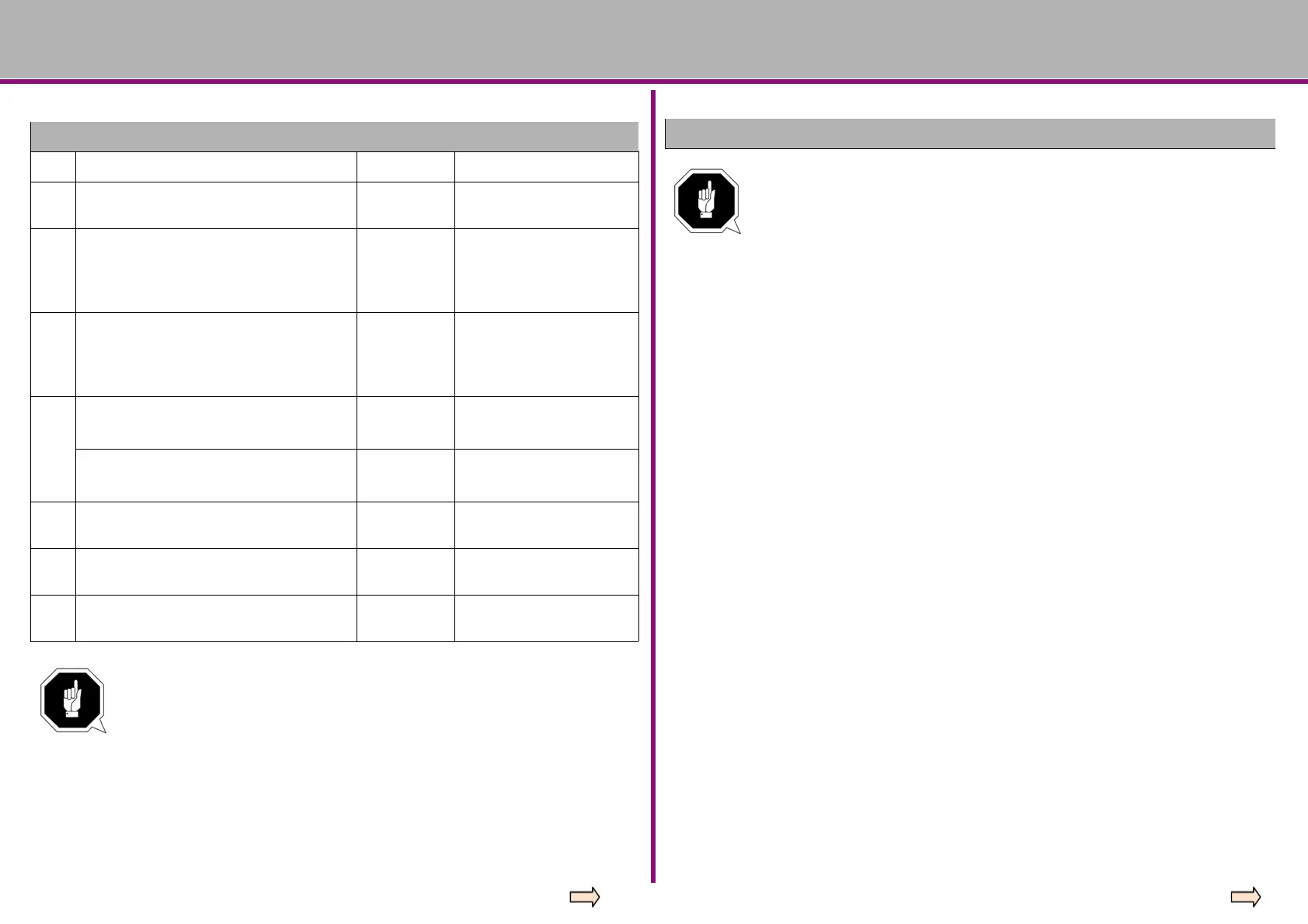
P. Descriptions Unit Applied range and note
G73 fast-speed deep hole drilling
Common programming structures:
G73 X—Y—Z—R—Q—F—K
Motion process:
① Drilling motion (-Z) → intermediate
feed
② Motion at the bottom of the hole →
none
③ Retraction motion (+Z) → fast feed
G73 application example program:
M3 S1500 ;spindle rotation
G90 G99 G73 X0 Y0 Z-15 R-10 Q5 F120
;after orientation drill 1st hole, back to R point
Y-50 ;after orientation drill 2nd hole, back to R point
Y-80 ;after orientation drill 3rd hole, back to R point
X10 ;after orientation drill 4th hole, back to R point
Y10 ;after orientation drill 5th hole, back to R point
G98 Y75 ;after orientation drill 6th hole, back to R point
G80 ;cancel fixed cycle
G28 G91 X0 Y0 Z0 ;back to reference point
M5 ;spindle rotation stop
M30
For the meaning of letters when programming typical fixed cycles,
please refer the figure on the left!
G74 reverse tapping cycle
Common programming structures:
G74 X—Y—Z—R—P—F—K
Motion process:
① Drilling motion(-Z) → cutting feed
② Motion at the bottom of the hole →
spindle rotation in positive direction
③ Retraction motion(+Z) → cutting feed
G74 application example program:
M4 S100 ;spindle rotation
G90 G99
G74 X300 Y-250 Z-150 R-120 P300 F120
;after orientation drill 1st hole, back to R point
Y-550 ;after orientation drill 2nd hole, back to R point
Y-750 ;after orientation drill 3rd hole, back to R point
X1000 ;after orientation drill 4th hole, back to R point Y-
550 ;after orientation drill 5th hole, back to R point G98
Y750 ;after orientation drill 6th hole, back to R point G80
;cancel fixed cycle
G28 G91 X0 Y0 Z0 ;back to reference point
M5 ;spindle rotation stop
M30





 To Next Page