Mechanical Installation 41-
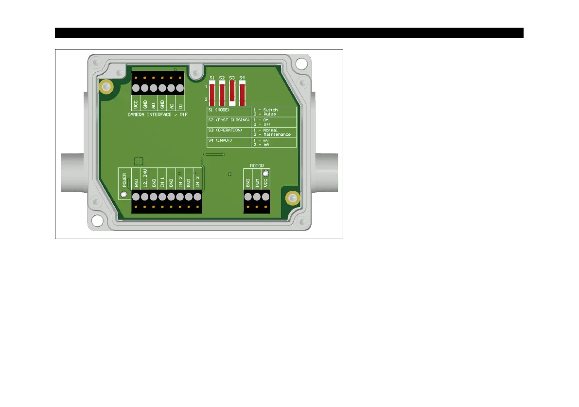
Figure 16: Control box of shutter, dimensions (see Figure 8)
Power supply: 12-24 V
Upper terminal screw Connection
for Process Interface (PIF)
Switch for different operation
modes:
S1: Switching between switch
operation and pulse operation
S2: Activation/deactivation of fast-
closing mode
S3: Only for factory calibration
(Switch must be at Normal)
S4: Switching between mV or mA
input
Lower screw terminal: Connection for power supply,
Inputs (Start/Stop signal) and Motor
Inputs (Start/Stop signal, max. 24 V, input is
active LOW (open input = HIGH)):
IN 1: Trigger input for normal operation (S1)
IN 2: Currently no usage
IN 3: Trigger input for fast-closing mode (S2)