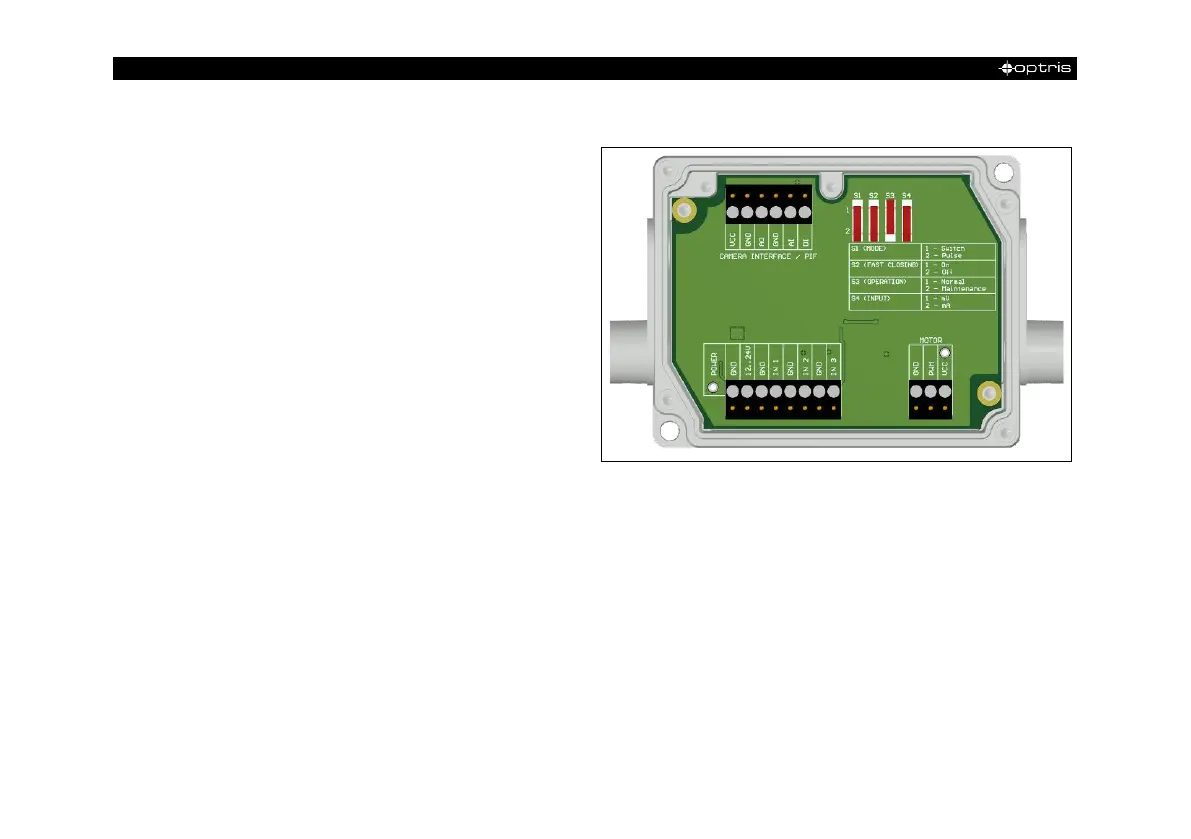
The shutter system is supplied with a control box
(for pin assignment, see also Figure 16). The
servo motor of the shutter is connected to this
control box. There are several ways to operate
the control box. For all listed options, an input
signal (IN 1) must be connected. This input signal
can, for example, come from a PLC, a light
barrier or a sensor. This signal opens and closes
the shutter. A second input signal (IN 3) can be
used to realize a fast-closing mode. The closing
time in this mode is only 100 ms.
By using the process interface (PIF), the input signal to the software can be passed on and used as a trigger
signal in the software. For example, an automatic recording can take place when the shutter is opened.
The process interface cable supplied with the cameras can be connected directly to the control box (upper
terminal block: CAMERA INTERFACE / PIF). Alternatively, the separately obtained industrial or stackable
PIF can also be connected to the control box (if several outputs and inputs are used). In this case, the
outputs and inputs used (e.g. AO from control box with AO from PIF) must be connected with each other.