Table 11-2 (Cont.) Series 2 Cash Drawer Pin and Signal Reference
Pin # Signal Name Description
3, 7, 8 Ground Signal grounds
4 CD_ST Input status from cash drawer
5 MCU_TX_5V Tx data to cash drawer
6 MCURX Rx data from cash drawer
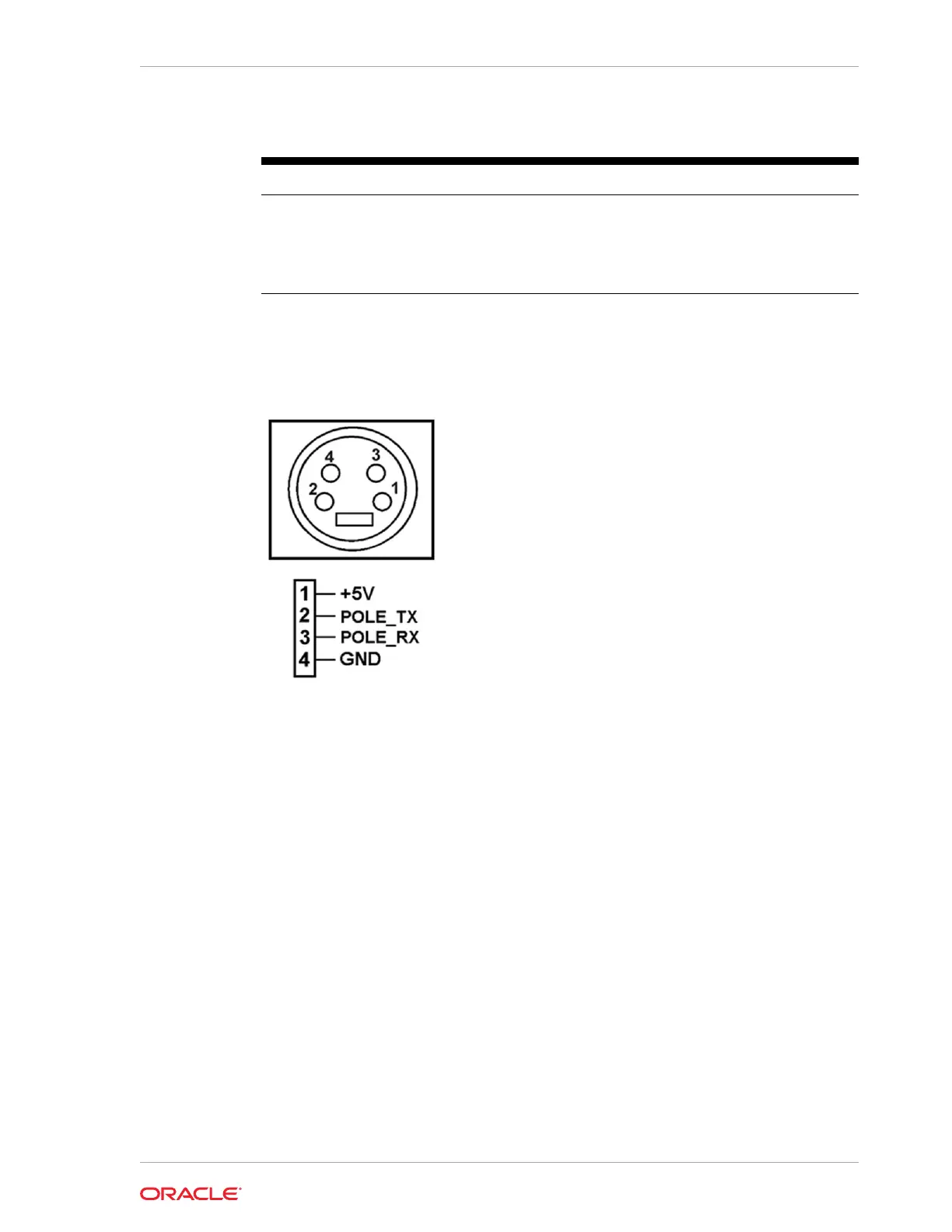
Customer Display
The customer display port contains the following pins:
System Block Diagrams
The diagrams in this section depict the system block diagrams for the 610, 620, and
650 configurations.
• 610 Configuration
• 620 and 650 Configurations
610 Configuration
The following diagram depicts the Broadwell ULT Main Board for the 610 configuration
of the Workstation 6.
Chapter 11
System Block Diagrams
11-3
 Loading...