7420 Controller Hardware Overview
Figure Legend Figure Legend Figure Legend
1 Locator LED and button (white) 7 Power Supply (PS) Service
Required LED
13 SSD 2 (optional)
2 Service Required LED (amber) 8 Over Temperature Warning LED 14 SSD 3 (optional)
3 Power/OK LED (green) 9 USB 2.0 Connectors 15 SSD 4 (optional)
4 Power button 10 DB-15 video connector 16 SSD 5 (optional)
5 Service Processor (SP) OK LED
(green)
11 Boot drive 0 (mirrored)
6 Fan/CPU/Memory Service
Required LED
12 Boot drive 1 (mirrored)
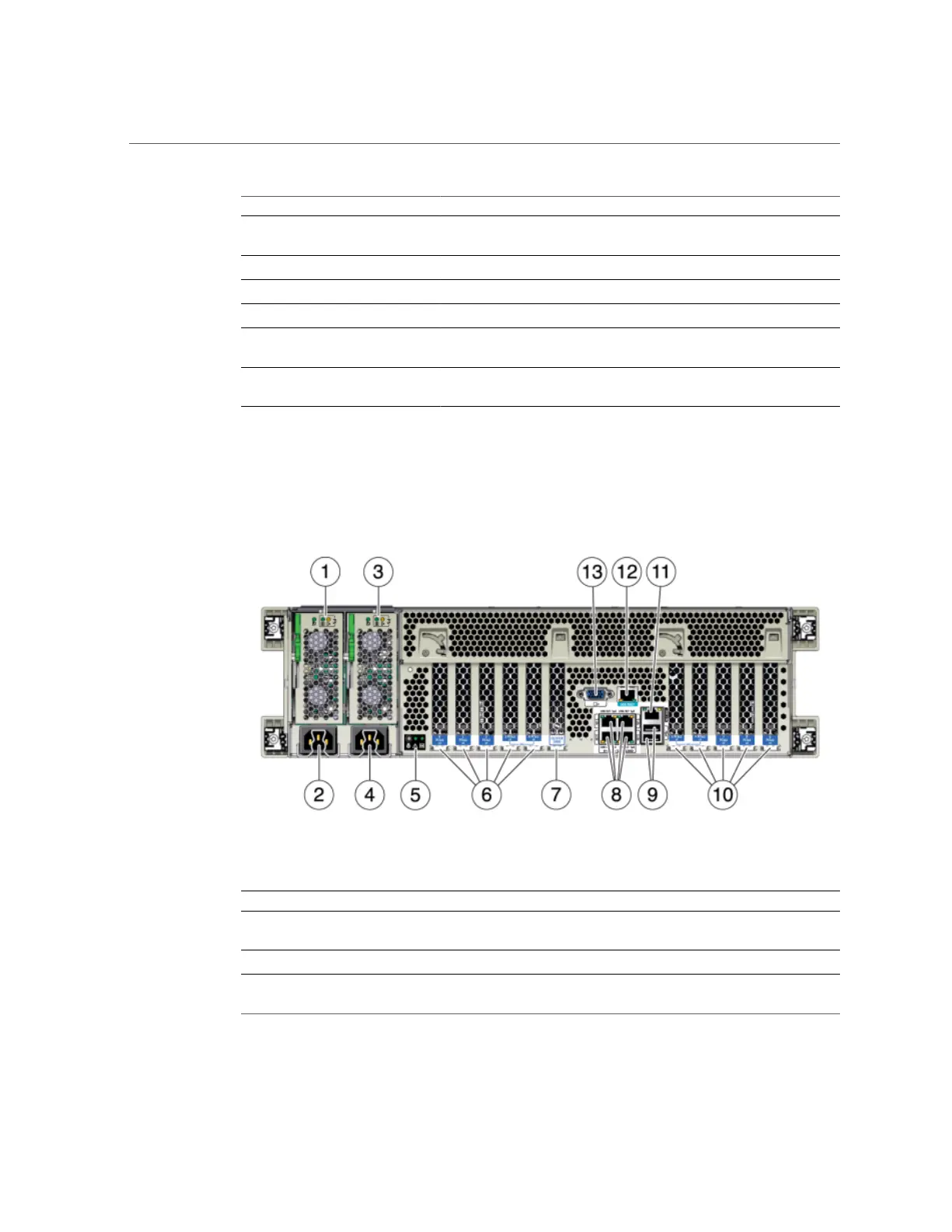
7420 Back Panel Components - The following graphic shows the rear panel of the controller.
Base configuration HBAs are not depicted in this illustration.
FIGURE 37
7420 Controller Rear Panel
Figure Legend Figure Legend
1 Power supply unit 0 status LEDs OK: green Power
Supply Fail: amber AC OK: green
8 Network (NET) 10/100/1000 ports: NET0-NET3
2 Power supply unit 0 AC inlet 9 USB 2.0 ports
3 Power supply unit 1 status LEDs OK: green Power
Supply Fail: amber AC OK: green
10 PCIe slots 5-9
216 Oracle ZFS Storage Appliance Customer Service Manual • July 2016

 Loading...


