ST 9100 - INSTALLATION GUIDE
1.2.5.2 LED Location and Operation
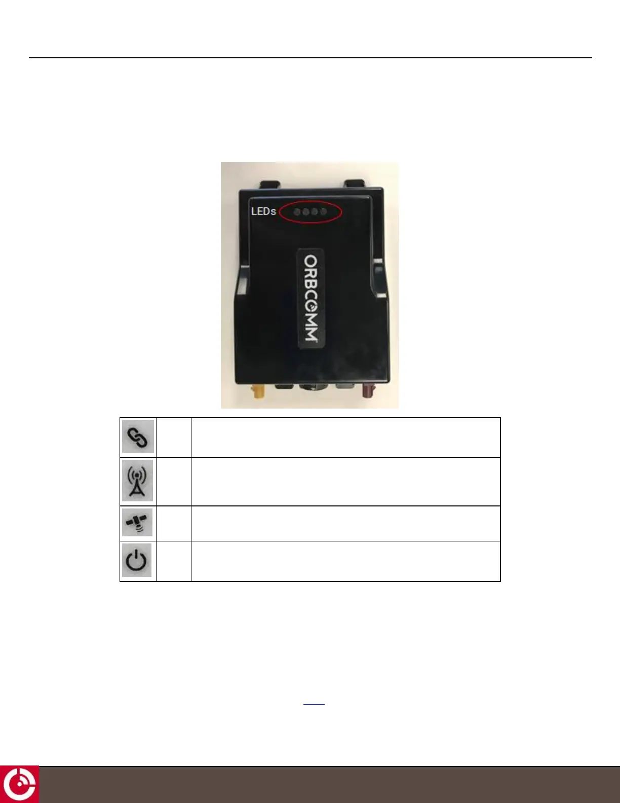
The transceiver has four visible LEDs (Figure 5) to indicate status.
Figure 5: LED Location
Sensor Indicates whether the terminal is receiving sensor data, or if paired with a sensor.
Cellular Indicates cellular communications status.
Satellite Indicates satellite communications status.
Power Indicates that the transceiver has external power.
1.2.5.3 LED User Control
After power on and ignition, you can control the LED by configuring the LED Control property to 1. The firmware
supports a function call (ledControl) that defines this operation. You can specify on time (msec), period (msec), and
number of repetitions (0 - 65535 where 0 signifies repeat forever).
This function allows a user service to flash the LED over a short period of time. The user service is responsible for
repeating this short pattern over a longer period. As an example, using the connection offline case from the previous
section, the LED control API allows a user service to flash the LED four times; the service is responsible for setting a
timer allowing it to restart this pattern every 30 seconds [T405].
T414, Version 0.04 BETA © ORBCOMM
®
Proprietary
13