ST 9100 - INSTALLATION GUIDE
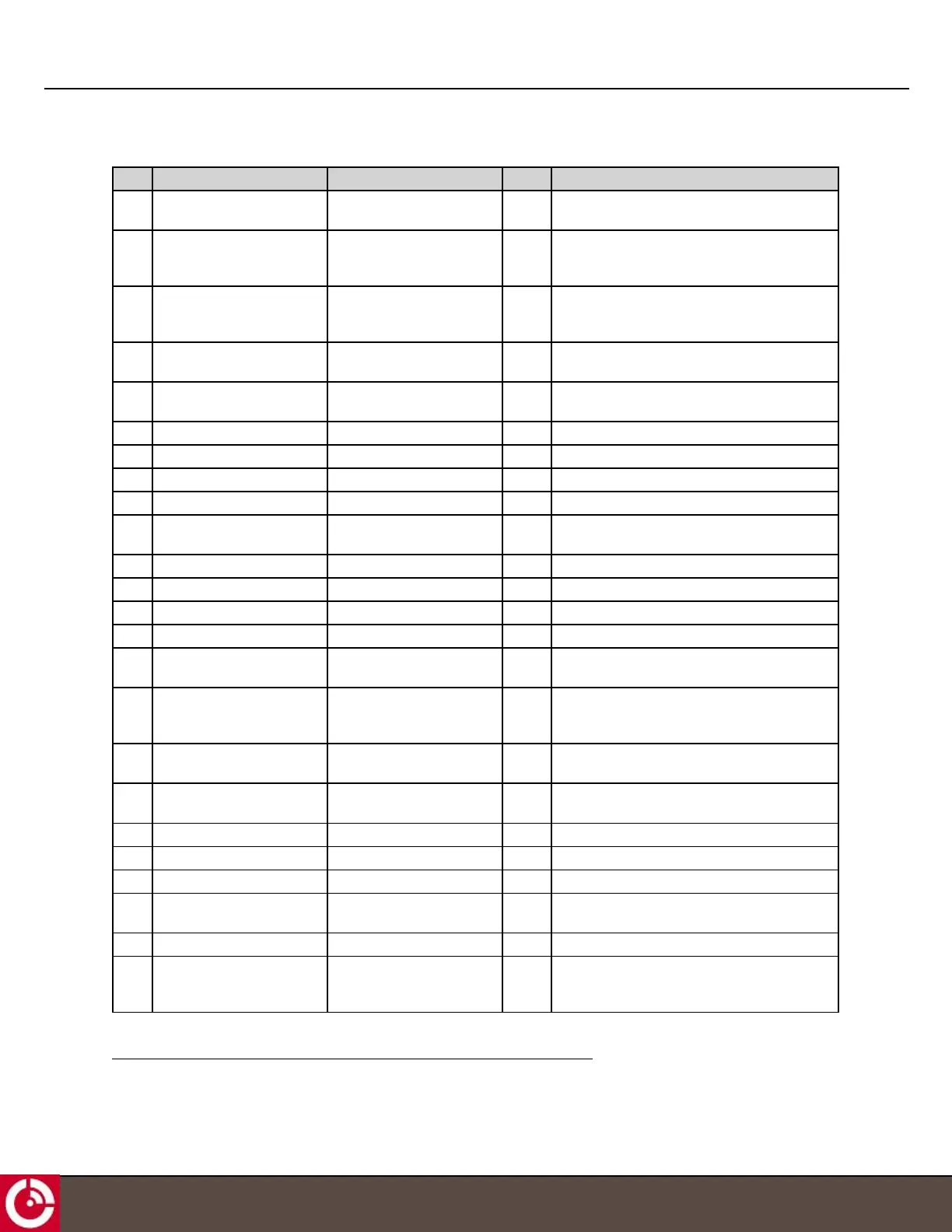
Table 2: Blunt-Cut Cable Electrical Pin Assignment
PIN Function Color
1
Type Description
1 RS485_A Blue I/O Half duplex RS485 driver output or receiver input
(complementary to RS485_B)
2 Digital/Analog_IN4 /
0-5 V_IN4 /
P2_4-20 mA
Orange/Black I Digital input or 0-5 V analog input or 4-20 mA
3 Digital/Analog_IN2 /
0-5 V_IN2 /
P1_4-20 mA
Pink I Digital input or 0-5 V analog input or 4-20 mA
4 I/O_4 Orange I/O Multifunction GPIO, push-pull, analog input,
current limited current sink and ignition load
5 I/O_2 Yellow I/O Multifunction GPIO, push-pull, analog input and
current sink
6 Ground Black (22 AWG) PWR External supply ground return
7 External Voltage Red (22 AWG) PWR External 9-32 VDC supply
8 Output_6 Black/White O Open drain output
9 1Wire Com Red/White PWR 1-WIRE return path
10 Console_RS232_TX Orange/White O ±15 kV ESD protected, RS-232 level (nominally
±5.5 V) transmitter outputs
11 AUX_RS232_RX Red/Black I TTL/CMOS level receiver outputs
12 CAN1_H Brown I/O High level CAN BUS line
13 CAN1_L Brown/White I/O Low level CAN BUS line
14 CAN0_L Green/White I/O Low level CAN BUS line
15 RS485_B Blue/White I/O Half duplex RS485 driver output or receiver input
(complementary to RS485_A)
16 Digital/Analog_IN1 /
0-5 V_IN1 /
P1_4-20 mA+
Light Green I Digital input or 0-5 V analog input or 4-20 mA
17 I/O_3 Purple I/O Multifunction GPIO, push-pull, analog input and
current sink
18 I/O_1 Black I/O Multifunction GPIO, push-pull, analog input and
current sink
19 Output_5 Purple/White O Open drain output
20 1Wire_DATA Yellow/Black I/O Input/output driver for 1-Wire Line
21 Console_RS232_RX Green/Black I TTL/CMOS level receiver outputs
22 AUX_RS232_TX Gray/Black O ±15 kV ESD protected, RS-232 level (nominally
±5.5 V) transmitter outputs
23 CAN0_H Green I/O High level CAN BUS line
24 Digital/Analog_IN3 /
0-5 V_IN3 /
P2_4-20 mA+
White I Digital input or 0-5 V analog input or 4-20 mA
1
24 AWG unless noted otherwise.
T414, Version 0.04 BETA © ORBCOMM
®
Proprietary
37