ST 9100 - INSTALLATION GUIDE
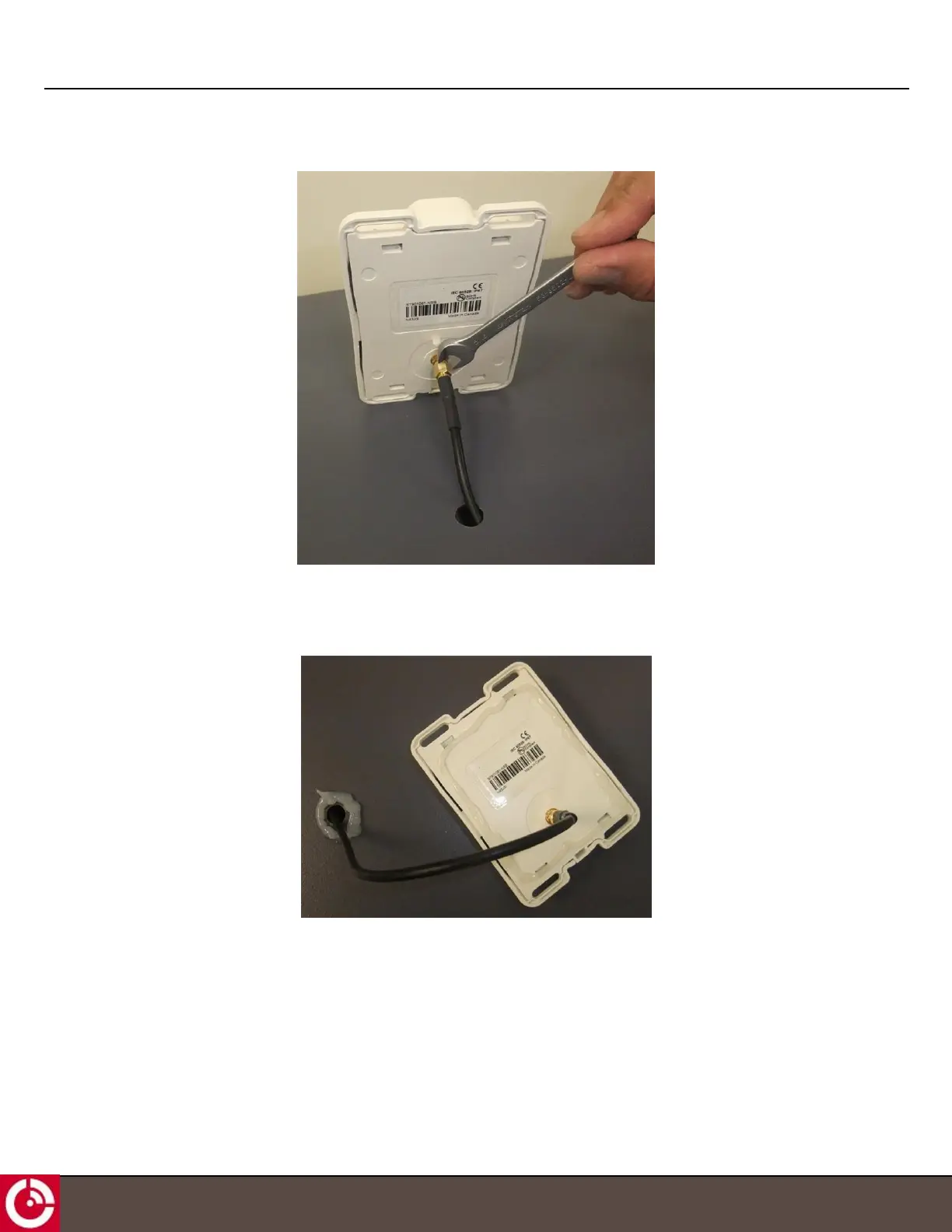
Figure 8: Attach Cable to Transceiver
5. Apply silicone around the hole in the asset and to the bottom surface of the antenna.
Figure 9: Apply Silicone to Hole in Asset
6. Lower the antenna onto the mounting surface.
The straight SMA cable connector can be lowered straight down onto the mounting surface.
The right-angle SMA cable connector, not shown, must be pivoted down onto the mounting surface to fit the
right-angle cable and connector through a larger clearance hole. Additional care is required with this
installation to ensure the right-angle cable and connector does not smear the silicone around the clearance
hole when attempting to pivot the antenna into position.
T414, Version 0.04 BETA © ORBCOMM
®
Proprietary
18