Regulations and standards
−37−
12.5 Installing and wiring in compliance with EMC Directive
The EMC Directive requires that your mechanical equipment in which the product is installed satises the applicable
requirements.
The installation and wiring methods of the motor and speed controller explained here represent the basic methods that
are eective in helping your mechanical equipment conform to the EMC Directive.
The nal level of conformance of your mechanical equipment to the EMC Directive will vary depending on such factors
as the control system equipment used with the motor and speed controller, conguration of electrical parts, wiring,
layout and hazard level. It therefore must be veried through conducting EMC measures on your mechanical equipment.
Eective measures must be taken against the EMI that the product may give to adjacent control-system equipment, as
well as the EMS of the product itself, in order to prevent a serious functional impediment in the mechanical equipment.
The use of the following installation and wiring methods will enable the product to be compliant with the EMC Directive.
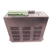
Connecting mains lter for AC power supply line
Install a mains lter, which the customer provides, in the power line in order to prevent the noise from propagating via
the AC power line. For a mains lter, use the following model or equivalent product.
Manufacturer Model
SOSHIN ELECTRIC CO.,LTD NF2010A-UP
Schaner EMC FN2070-10-06
Install the mains lter as close to the speed controller as possible. Use cable clamps and other means to secure the
input cables and output cables of the mains lter rmly to the surface of the enclosure. Connect the ground terminal
of the mains lter to the grounding point, using as thick and short a wire as possible.
Do not place the input cable parallel with the output cable. Parallel placement will reduce mains lter eectiveness if
the enclosure's internal noise is directly coupled to the AC power supply cable by means of stray capacitance.
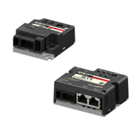
Connecting motor cable
When extending the motor cable, use an accessory connection cable (sold separately).
The wiring distance can be extended to a maximum of 10.5 m (34.4 ft.).
Surge arrester
A surge arrester is eective for reduction of the surge voltage of the lightning surge generated between the AC power
line and earth or between AC power lines. Connect the following surge arrester.
Manufacturer Model
SOSHIN ELECTRIC CO.,LTD LT-C12G801WS
Wiring of the control cable
Use a cable of AWG24 (0.2 mm
2
) or thicker for the control cable, and keep the wiring distance as short as possible [2 m
(6.6ft.) or less].
Notes about installation and wiring
Connect the motor, speed controller, and other peripheral control equipment directly to the grounding point so as to
prevent a potential dierence from developing between grounds.
When relays or electromagnetic switches are used together with the product, use mains lters or CR circuits to
suppress surges generated by them.
Keep cables as short as possible without coiling and bundling extra lengths.
Wire the power lines such as the AC power cable and motor cable away from the signal cables by providing a minimum
clearance of 100 mm (3.94 in.) between them. If the power lines (AC power cable, motor cable) and signal cables have
to cross, cross them at a right angle.
Use an accessory connection cable (sold separately) when extending the wiring distance between the motor and
speed controller. The EMC testing is conducted using the Oriental Motor connection cable.
 Loading...