Preparation
−7−
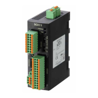
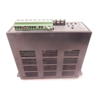
3.5 Names and functions of parts
Display
Operation keys
POWER LED
(Green)
Main circuit connector
(CN1)
ALARM LED
(Red)
DIN lever
Control circuit connector
(CN4)
Motor connector
(CN3)
Protective lm
(Use after removing the protective lm.)
Operation panel
Sink logic/Source logic
select switch (SW1)
Item Display Overview
Reference
page
Operation panel
Display
The rotation speed, parameter, alarm and others are
shown on the display.
P.24
Operation keys
MODE
<
>
SET
These keys are used to switch the operation mode, set the
operation data or change the parameter.
POWER LED (Green) POWER
This LED is lit while the AC power is supplied to the speed
controller.
P.16
ALARM LED (Red) ALARM This LED blinks while an alarm generates. P.30
Motor connector (CN3) CN3 MOTOR Connects the motor connector.
P.11Main circuit connector (CN1) CN1 Connects the AC power supply, capacitor and FG.
Control circuit connector (CN4) CN4 I/O Connects the control DC power supply and I/O signals.
Sink logic/Source logic select switch
(SW1)
SW1
This switch is used for switching the input signal between
sink logic and source logic modes.
P.15
DIN lever
This is used to mount the speed controller to a DIN rail.
The speed controller can also be mounted using screws.
P.9