IG-273-EN version 03; 05/08/2020
25
General instructions
cpg.0 ENA range
Installation
6.6.1. cpg.0-v/cpg.0-l/cpg.0-pt/cpg.0-rb
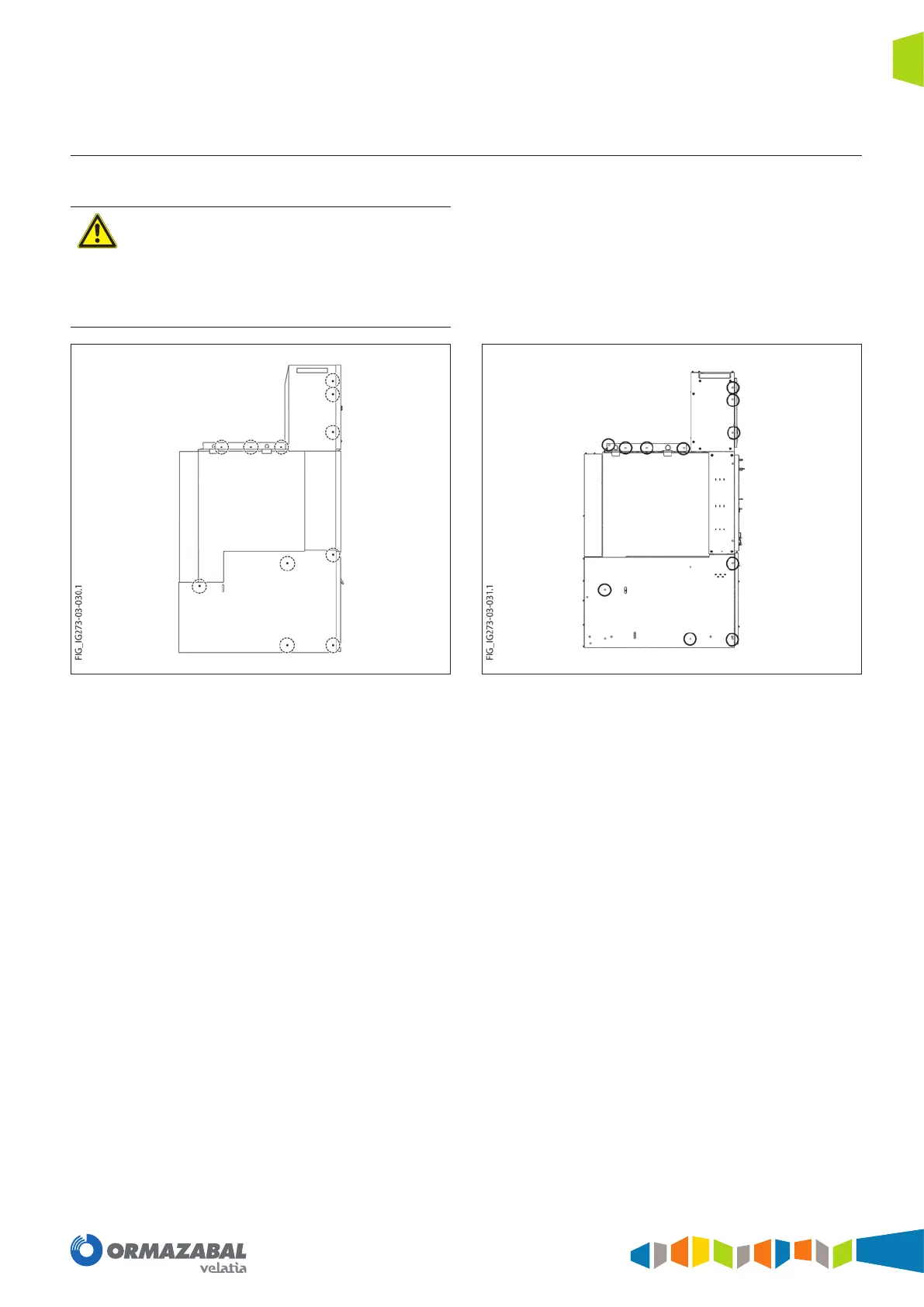
The xing points are dened in Figure 6.11 and Figure 6.12:
Ensure:
- The front faces of the units are ush and in alignment.
- The top edge of the bolting ange in the busbar
chamber must be aligned and level with the adjacent
unit.
- There should be no gaps between the bolted faces.
Figure 6.11. Fixing points up to 1250 A
Figure 6.12. Fixing points up to 2000/2500 A

 Loading...
