IG-273-EN version 03; 05/08/2020
6
General description General instructions
cpg.0 ENA range
1.3. Main components
1
Busbar compartment
2
Gas tank
3
Gas pressure relief duct
4
Cable compartment
5
Low-voltage control compartment
6
Driving mechanism compartment
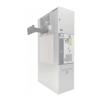
Figure 1.1. Main elements of cpg.0 cubicles
Gas tank
This is a sealed compartment made of stainless steel and
sealed for life which houses the switching and breaking
devices, with SF
6
gas as the insulating medium.
Figure 1.2. Bushing position in gas tank (1)
Depending on the function for which the cubicle was
designed, it may contain the following components:
• Disconnector.
• Earthing switch.
• Internal busbar and connections.
• Vacuum circuit-breaker.
It can be connected to the busbar and the medium-voltage
cables respectively by means of bushings at the top and
bottom.
The gas pressure is conrmed in each cubicle by means
of a pressure switch with a potential-free contact, allowing
it to be used as a remote alarm or blocking/trip for the
specic cubicle.
Busbar compartment
The busbar compartment, also designed to withstand an
internal arc, is located above the gas tank and separated
from the gas compartment. It is made from metal sheet,
oering the degree of protection necessary for the busbar
connection device.
It comprises a fully assembled, tested unit, with solid,
screened insulation.
Figure 1.3. Example of busbar compartment
Toroidal current transformers and/or plug-in voltage
transformers can also be installed in the busbar
compartment, thus avoiding the need for metering
cubicles.

 Loading...