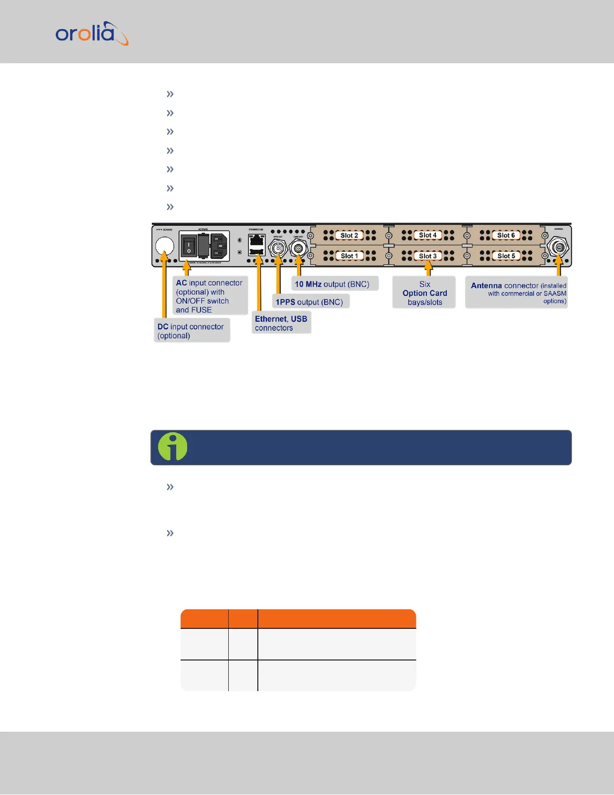
Optional AC connection for the power input
Optional DC power connector
Ethernet and USB connections
1PPS output
10 MHzoutput
Six bays for option cards
One optional antenna connector.
Figure 1-2: Standard rear panel
Typically, option cards will be installed at the factory.
The DC Power port connector is only installed if your unit was ordered with a DC input
power option.
Note: DC input power does not have an ON/OFF switch.
The ACPower connector is the input for the ACpower and provides an ACpower
ON/OFF switch. This connector assembly is only installed if SecureSync was
ordered with AC input power option.
The Ethernet connector provides an interface to the network for NTP syn-
chronization and to obtain access to the SecureSync product Web UI for system
management. It has two small indicator lamps, “Good Link” (green LED), and “Activ-
ity” (orange LED).
Table 1-1:
Ethernet status indicator lights
LED State Meaning
Orange
On
Off
LAN Activity detected
No LAN traffic detected
Green
On
Off
LAN Link established, 10 or 100 Mbps
No link established
1.2 Unit Rear Panel
SecureSync Getting Started Guide Rev. 12.0 7