Do you have a question about the Orolia SecureSync 1200 and is the answer not in the manual?
Details the components and layout of the SecureSync front panel, including LEDs, keypad, and display.
Describes the meaning of the POWER, SYNC, and FAULT status LEDs indicating the unit's operational status.
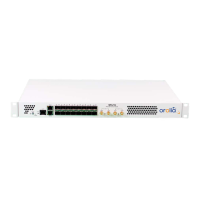
Details the connectors and bays found on the rear of the SecureSync unit for inputs and outputs.
Covers AC and DC power input requirements, voltage ranges, and maximum power draw for the unit.
Specifies the type, model, and quantity of fuses used in the SecureSync unit.
Details the GNSS receiver model and compatible signals, including frequencies and tracking capabilities.
Describes the function, connector, and character structure of the front panel serial port for configuration.
Explains the Ethernet port's function for NTP, SNTP, and remote management and configuration.
Details the 1PPS output signal characteristics, level, pulse width, rise time, and accuracies.
Describes the 10 MHz sine wave output signal, its level, harmonics, spurious emissions, and signature control.
Lists the physical dimensions and weight of the SecureSync unit, including rack mount compatibility.
Explains the HOME screen content, including system status, references, performance data, and log events.
Explains the meaning of various safety symbols (DANGER, CAUTION, NOTE, ESD, GROUND) used in the document.
Highlights critical dangers related to improper use, installation, opening equipment, and fusing.
Emphasizes the necessity of proper earth grounding for the unit via AC and DC power connectors.
Outlines user responsibilities for safe operation, including equipment condition, skills, and using authorized parts.
Advises on precautions for handling equipment sensitive to electrostatic discharge (ESD).
Lists necessary components for using a GNSS reference input, such as antenna, cabling, and surge suppressor.
Provides detailed steps for mounting the unit in a standard 19-inch rack cabinet using provided and customer-supplied hardware.
Explains the rules for power source selection when both AC and DC inputs are connected to the unit.
Warns about the implications of having multiple power sources connected and the effect of the rear panel power switch.
Details how to connect the AC power cord to the unit and use the AC input, including fuse protection.
Explains how to connect DC power, including available voltage options, current requirements, and polarity protection.
Describes connecting the unit to a network via a hub or router using a straight-through Ethernet cable.
Explains direct connection to a PC, requiring static IP configuration for both devices.
Describes the LED indicators and information display during the unit's startup and boot-up sequence.
Outlines three methods for network communication: Web UI, CLI, and front panel display.
Explains how to find the unit's IP address via front panel display, CLI, or Web UI.
Provides instructions for disabling or enabling DHCP on the unit's Ethernet port via the front panel.
Details how to configure static IP addresses, netmask, and gateway via front panel, CLI, or Web UI.
| Brand | Orolia |
|---|---|
| Model | SecureSync 1200 |
| Category | Network Hardware |
| Language | English |