Operator Manual
Display
Display
This section describes the practical use of the equipment and explains the LASER welder menu.
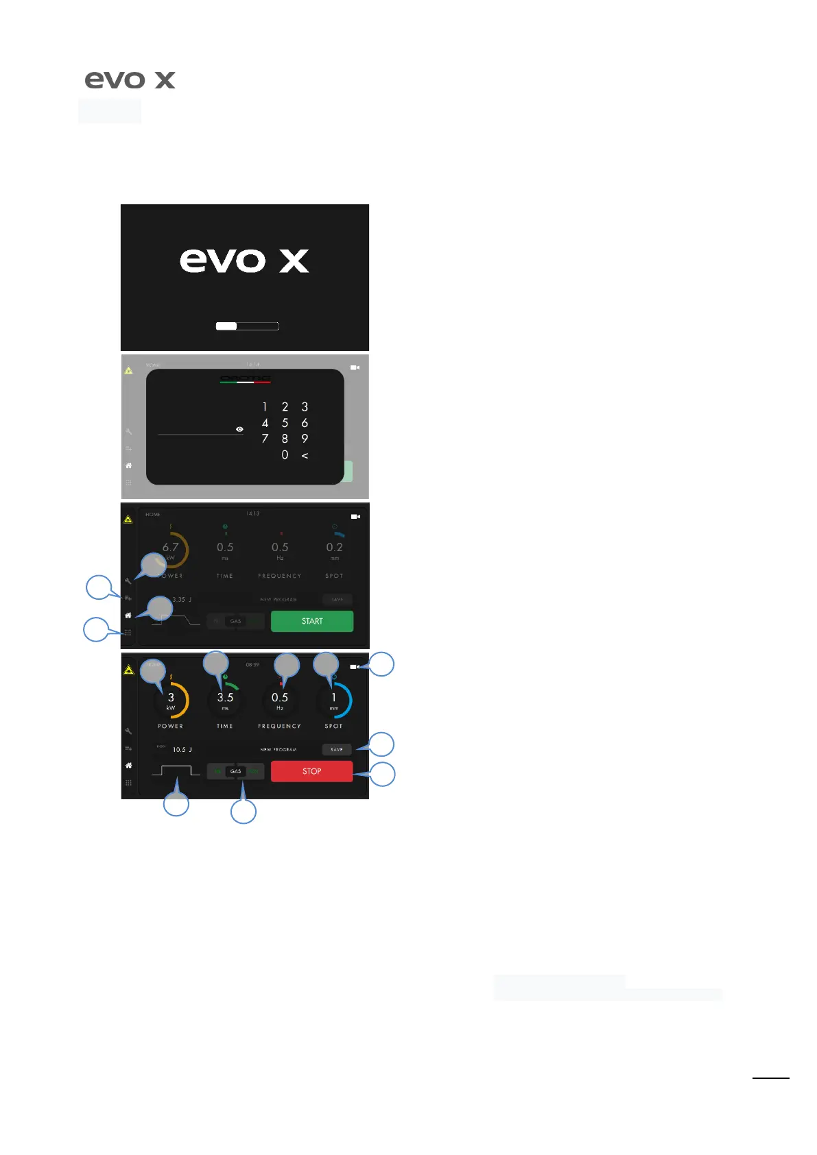
Display Screens
After having pressed the master switch, which is on the rear part of
the machine (see page 16), the uploading screen will appear. Wait
until the uploading bar is complete.
Before accessing the program HOME page, the unlocking PIN is
requested. Enter ”
” as default pin. The access PIN can be
changed in the settings.
The Home screen allows the machine to be started and the laser to
be armed by holding the START button down. The settings and
services icons are on the left.
Menu
Home
Welding Programs and Parameters
Settings.
WORK HOME PAGE
The is the main screen of the machine during the work phase. The
Power, Time,
Fr e quency, Spot
set points can be selected via touch-s creen and via the rotary
switch that is found inside the welding chamber. The settings for modification
of the pulse
(
), the
, the
and the
of programs, are only access ible via touch-screen. To disarm
the LASER and go back to the STAND-BY screen, hold the STOP button down.
The power of the LASER pulse can be set from 0.5kW to
6kW with steps of 0.1kW.
Duration of the LASER pulse can be set from 0.5ms to 25ms
with steps of 0.1ms.
: The frequency of the LASER pulse can be set from 0Hz
(Single shot every time pedal is pressed) to 20Hz with steps of 1Hz.
By holding the pedal down, the shot frequency will follow the value
set.
LASER pulse wave form.
: the first time the pedal is pressed, the LASER
is not emitted, just the Gas.
: the solenoid valve is opened
emitting the Gas for the duration selected in the settings screen
(see SETTINGS screen).
The diameter of the welding spot, which can be set from 0.1
mm up to 2.0 mm with steps of 0.1 mm
Enabling of the camera to view the welding area. From
the settings screen it is possible to set the automatic passage from
the parameters screen to the camera after 5 seconds.
Possibility to save the parameters
13) S t o p: machine shut down and "Stand-by” Home screen display.
5
6
7
10
9
8
11
13
4
3
1