7.Demonstration
(3) Push the CH1 to CH4 button to turn on CH1 and CH2, turn off CH3 and
CH4.
(4) Push the Autoset button, with the oscilloscope turning on the signals of
the two channels and displaying them in the screen.
(5) Push CH1 button to select CH1, turn the lower knob, and then push CH2
button to select CH2, turn the lower knob, making the amplitudes of two
signals equal in the rough.
(6) Click to call up the menu panel. Click the XY softkey on panel to switch
to the ON state. The oscilloscope will display the input and terminal
characteristics of the network in the Lissajous graph form.
(7) Turn the upper and lower knobs, optimizing the waveform.
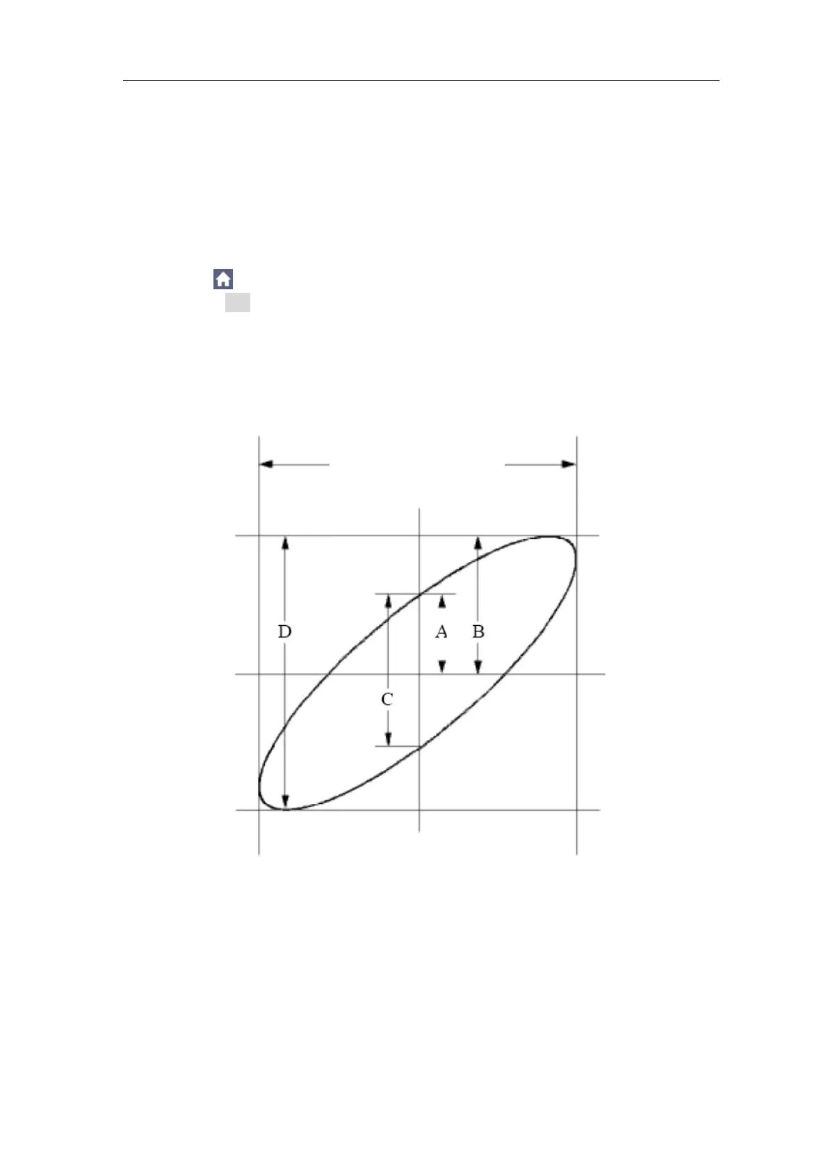
(8) With the elliptical oscillogram method adopted, observe and calculate the
phase difference (see Figure 7-6).
Figure 7-6 Lissajous Graph
Based on the expression sin (q) =A/B or C/D, thereinto, q is the phase
difference angle, and the definitions of A, B, C, and D are shown as the graph
above. As a result, the phase difference angle can be obtained, namely, q =±
arcsin (A/B) or ± arcsin (C/D). If the principal axis of the ellipse is in the I and
III quadrants, the determined phase difference angel should be in the I and IV
quadrants, that is, in the range of (0 - π /2) or (3π / 2 - 2π). If the principal axis
of the ellipse is in the II and IV quadrants, the determined phase difference
angle is in the II and III quadrants, that is, within the range of (π / 2 - π) or (π -
The signal must be
centered and kept in the
horizontal direction.
 Loading...