2 x OXY0011
4mm-Linkage Ball
2 x OXY0010
Threaded Rod M1.6 X 14
Carbon Fiber Tail Push Rod Assembly.
(CNC components - Inside Tail Boom)
CF Push Rod
4mm
4mm
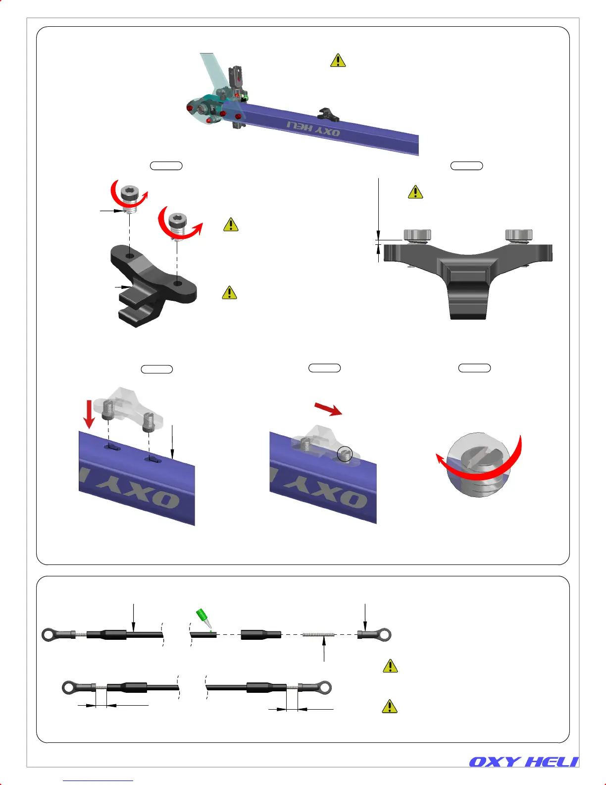
2 x OXY0068
Pin Screw
OXY0067
Guide Push Rod
Note: To install this
pin screw rotate
counter clock wise.
>=0.5mm
A
Main Frame
OXY0065
Tail Boom
11X14X0.5X284
Push the part inside
boom socket as shown.
Page 8
Plastic Linkage have Lynx logo to give you
information about the turn adjustment,
but have symmetrical ball socket shape
and can be installed in both directions to
achieve the best fine tuning operation.
Slide the parts as shown.
In order to lock tail push rod
support, use Flat Screw Driver
and turn clockwise. Do not
over tighten.
Note Pin Screw Thread :
Oxy design Pin Screw with counter
clockwise thread. This will help on
the final locking operation. Be careful
to follow our instruction to get perfect
assembly.
Note: Install Pin Screw and leave
shown space for final assembly.
Step 1 Step 2
Step 3
Step 4 Step 5
Detail A
Tail Case
Tail Push Rod Guide Assembly.
(CNC components).
Important Note:
Plastic Terminals and CF Push Rod come
pre assembled with CA superglue for
quality reason. Ready to use.
Important Note:
This part come already pre
assembled. Ready to Use.
Chapter 6, Boom Assembly