SECTION 3 INSTALLATION
Pacific Power Source ©2013 3-6 Document # 126050-10 Rev E
3.3 CHANGING INPUT VOLTAGE
Configure the system for the correct input voltage prior to installing. All voltages
listed in this procedure are line to line.
When changing the input voltage, the input circuit breaker and fuses must also
be changed to accommodate the different current required. The input
transformer, T1, and LVPS transformer, T2, must be reconnected to the correct
taps. See figure 3.3.1 through figure 3.3.4.
Each mainframe, dependent upon model number, will require the following Input
Circuit Breaker and Fuses:
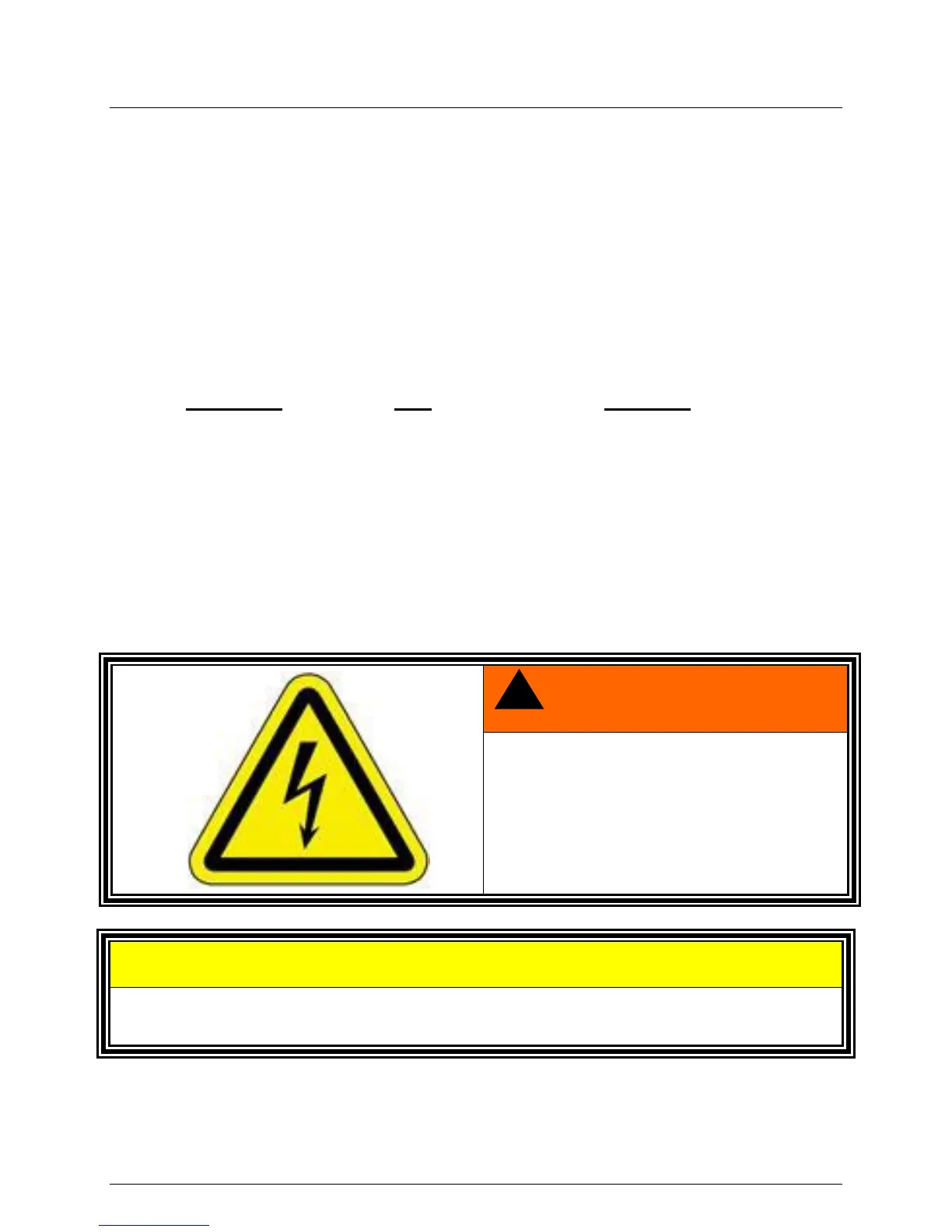
ELECTROCUTION HAZARD.
OPENING INPUT CONTACTOR DOES
NOT REMOVE INPUT VOLTAGE FROM
INPUT TRANSFORMER. FOR SAFETY,
OPEN THE INPUT CIRCUIT BREAKER.
DAMAGE TO THE EQUIPMENT MAY RESULT IF INCORRECTLY WIRED. VERIFY
CONNECTIONS ARE MADE TO PROPER TAPS.
 Loading...