SECTION 6 SERVICE
Pacific Power Source ©2013 6-17 Document # 126050-10 Rev E
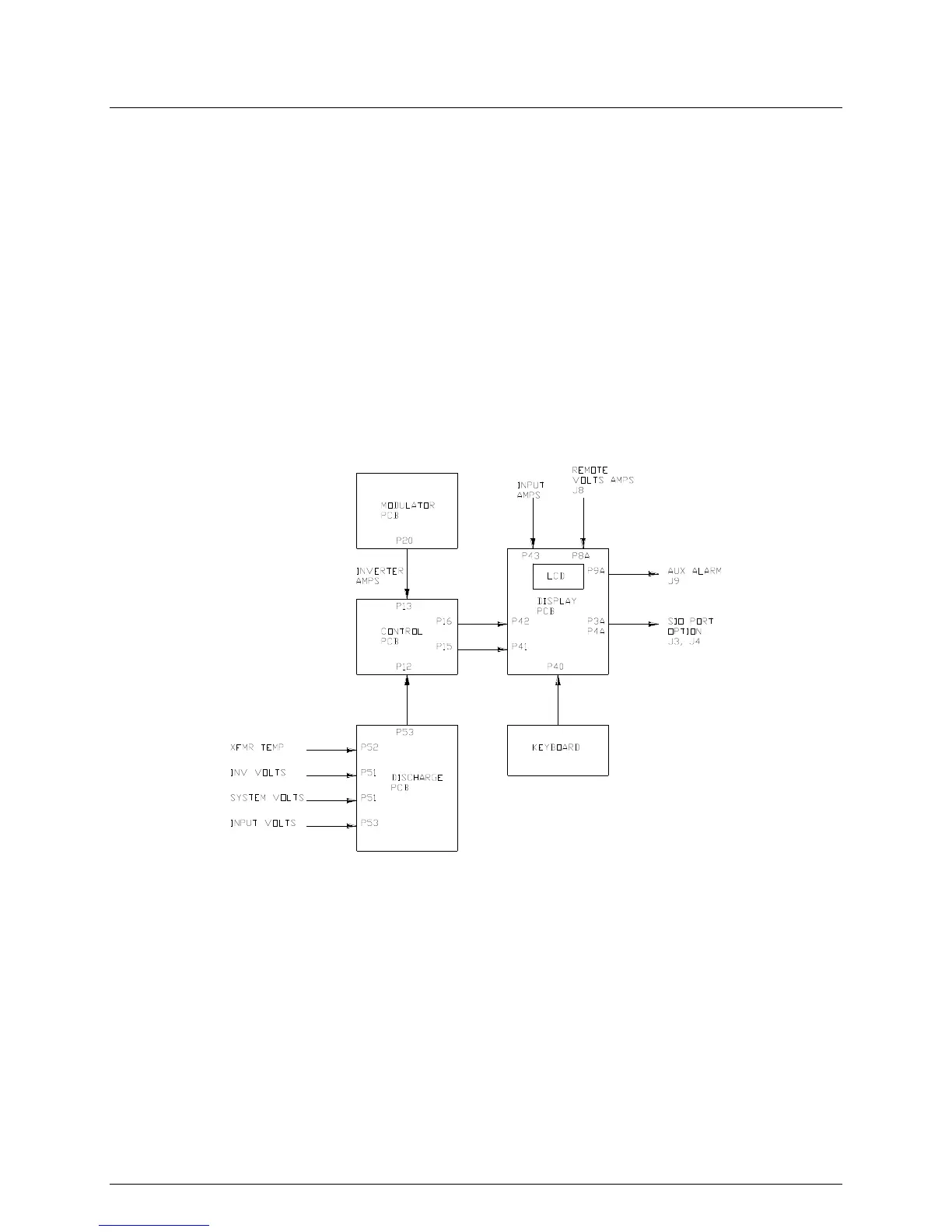
6.2.4 THEORY OF OPERATION - DISPLAY CIRCUITS
The Display PCB is mounted to the rear of the keyboard sub-panel. The
metering circuits are contained on the Display PCB assembly. A CPU is used to
meter and display system information on an LCD. The Discharge PCB assembly
contains the resistor voltage dividers to scale down system voltages to a low
level. These system voltages are sent to the Control PCB. The Control PCB
provides all input signals (analog and digital), except input amps, to the Display
PCB. CT11-CT13 provide the input current terms required by the Display PCB.
Figure 6.2.4 is the block diagram for the meter and display portion of the MS-
Series power source.
The Control PCB drives the EMER OFF, OFF, STANDBY, ON, MASTER and
SLAVE lamps.
FIGURE 6.2.4 BLOCK DIAGRAM DISPLAY CIRCUITS