52/164 cod. 00 477 1480 - 12/2012 - Palazzetti - PN - Italy
INSTALLATION
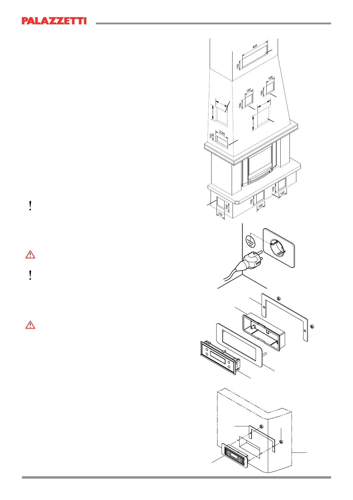
6.7 CREATION OF UTILITY HOLES ON
CLADDING
Utility holes must be made in the cladding for the
following:
A) display slot;
B) ventilation vents;
C) heat release in hood;
D) ventilation of cladding on base;
E) intake vents on base motor;
F) loading of pellets onto hood;
The holes must comply with the measurements
shown in Fig. 6.6.1.
6.8 CONNECTION TO SYSTEMS
6.8.1 Electrical connection
Simply connect the stove to the electricity mains
with the plug supplied.
)
access also after the stove has been installed.
If the power lead is damaged it must be replaced
electrician to prevent all risks.
6.8.1.1 Earthing
DANGER
6.8.2 Control panel installation
using box “A” or recessed using box “B” (not
included).
DANGER
Do not install the recessed box on the hood.
)
Place the passage of the cable between the panel
and the electronic card so that it is not damaged by
temperature.
Connect the cable between the terminals of the
electronic card and the control panel before closing
the boxes.
6.8.3 Connection to room thermostat
The stove is set up for connection to an external
room thermostat (in normally open position).
Where available, on the upright of the stove there
is the connector for the insertion of the cables C
of the room thermostat , terminals 1 and 2 as per
image (Fig.6.7.3).
295
295
295
295
A
B
F
F
B
C
D
E
Fig. 6.6.1
Fig. 6.7.1
Fig. 6.7.2
1
2
3
4
1
2
3
4