150
# 2 BLACK
# 4 BLACK
# 1 BLACK
GREEN / YELLOW
(+)
(-)
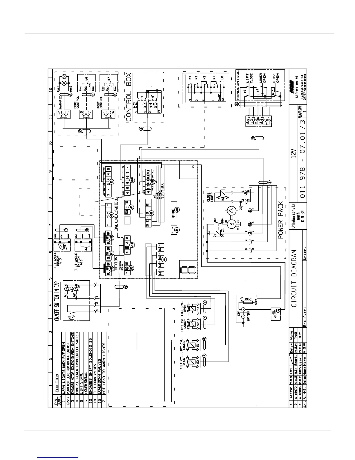
ILF 33/44/55 PLUS
CIRCUIT BOARD
OPEN
WIRELESS HANDCONTROL
OPTIONAL
Legend
:
gn : green
bl : blue
br : brown
wt : white
ye : yellow
sw / bk : black
gy : green-yellow
LI : Lift Up
LO : Lower Down
OP : Open Gate
CL : Close Gate
* Good voltage is the most important first step
in troubleshooting the litgate.
* Test voltage at the J11connection
between wire 4 and ground (min. 10 V).
* When testing for electricity on the individual
solenoid plug at the cylinder, always test voltage
between the two prongs on the plug itself.(min. 7 V)
* After troubleshooting, carefully close the rubber cap
and secure it with the plastic strap
.
CLOSE
LOWER
LIFT
HACKBARTH
* When testing the voltage on different
locations, always ground on plug J1.
Tilt - Up bypass -- J11 #4 min. 8.5 V
Power
LED