4.1 Confirming the I/O Number Allocations and First Word Number
4.1.1 Occupied I/O Area and I/O Allocations
In the FP7, digital data for analog output is allocated to the external output relay area and
processed. Furthermore, control I/O signals are allocated to the FP7 to process errors and clip
upper and lower output limits.
■
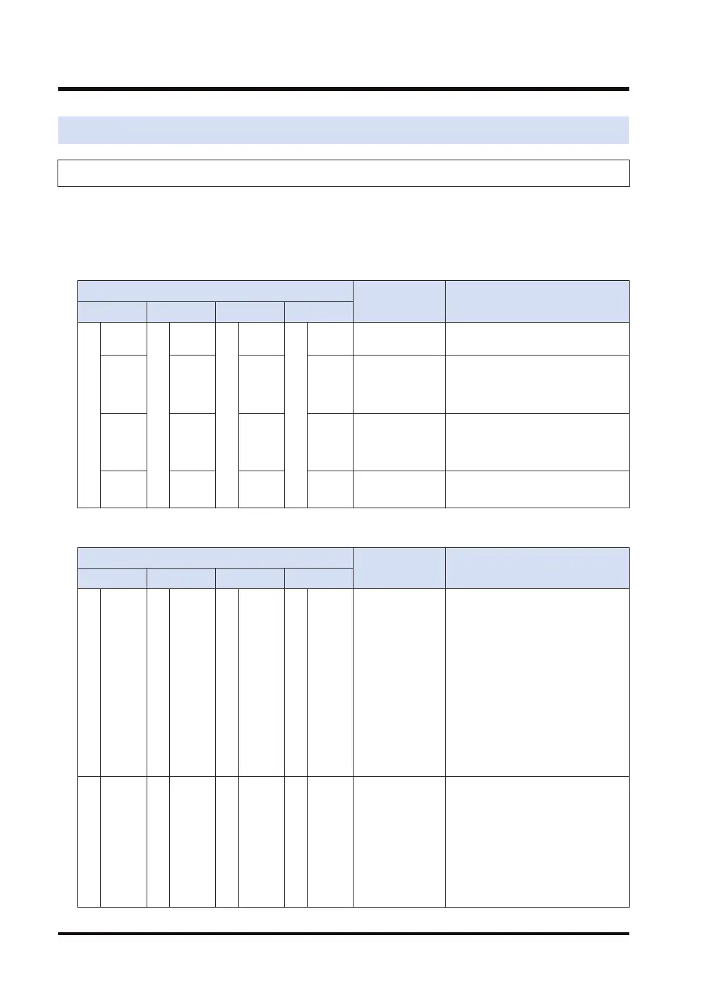
Input contact
Address
Name Description
CH0 CH1 CH2 CH3
WX0
X0
WX1
X10
WX2
X20
WX3
X30 Error flag
Turns ON when an error is
detected.
X1 X11 X21 X31
Upper limit of
upper and lower
output clipping
Turns ON when the output exceeds
the upper limit of output clipping,
provided that the upper and lower
limit function is active.
X2 X12 X22 X32
Lower limit of
upper and lower
output clipping
Turns ON when the output drops
below the lower limit of output
clipping, provided that the upper
and lower limit function is active.
X3 to
XF
X13 to
X1F
X23 to
X2F
X33 to
X3F
Not used Do not use.
■
Output contact
Address
Name Description
CH0 CH1 CH2 CH3
WY0
Y0 to
YF
WY2
Y20 to
Y2F
WY4
Y40 to
Y4F
WY6
Y60 to
Y6F
D/A conversion
data
(16 bit)
Set a digital value corresponding to
the analog output.
<Voltage range>
-10 to +10 V: -31,250 to +31,250
0 to +10 V or 0 to +5 V: 0 to
+31,250
+1 to +5 V: 0 to +25,000
<Current range>
+0 to +20 mA: 0 to +31,250
+4 to +20 mA: 0 to +25,000
* Apply a digital value within the set
scale if scale conversion is set.
WY1
Y10
WY3
Y30
WY5
Y50
WY7
Y70
Upper and lower
limit output
clipping function
execution relay
The upper and lower output limit
clipping function is executed with
the relay turned ON.
With the relay turned OFF,
the upper limit flag (Xn1) for upper
and lower output clipping limits
and the lower limit flag (Xn2) for
upper and lower output clipping
limits are turned OFF.
4.1 Confirming the I/O Number Allocations and First Word Number
4-2 WUME-FP7AOH-03