6.3 Settings for Upper and Lower Output Clipping
■
Overview of functions
This function makes it possible to clip the output with specified values in excess of the upper
and lower limit range if the specified values are set for digital output. This function makes it
possible to prevent the wrong application of voltages or currents out of the specifications to
equipment to be connected.
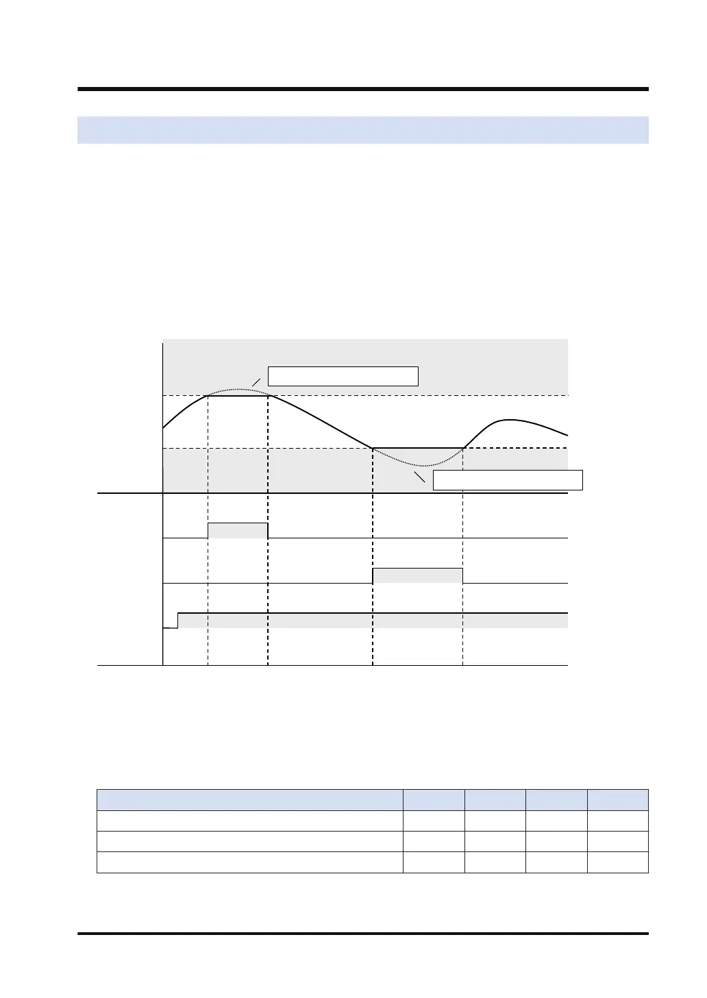
● Make output clipping settings for upper and lower limits on a channel-by-channel basis.
● The upper limit relay will turn ON if the digital output value is larger than the upper limit.
● The lower limit relay will turn ON if the digital output value is smaller than the lower limit.
● It is necessary to turn ON the execution relay with a user program in order to clip the upper
and lower output limits.
Upper limit
Lower limit
(K)
(Flag)
Digital
output
Upper limit
relay (*1)
Lower limit
relay (*2)
(t)
Digital output > Upper limit
Execution
relay (*3)
Digital output < Lower limit
■
I/O allocation
The I/O numbers in the timing chart and program are shown on the condition that the first word
number of the unit is "10".
Actual I/O numbers allocated are determined by the first word number.
CH0 CH1 CH2 CH3
*1 Upper limit of upper and lower limit clipping X101 X111 X121 X131
*2 Lower limit of upper and lower limit clipping X102 X112 X122 X132
*3 Function execution relay for upper and lower clipping Y110 Y130 Y150 Y170
6.3 Settings for Upper and Lower Output Clipping
WUME-FP7AOH-03 6-5