Reference
Connector pin assignment table
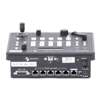
1 <CCU> connector
(Hirose Electric: HR10A-10R-10P (71))
Pin No. Function Polarity Flow of signal
1 CAM DATA (H) + CAM→ROP
2 CAM DATA (L) - CAM→ROP
3 CAM CONT (H) + ROP→CAM
4 CAM CONT (L) - ROP→CAM
5 CAM No.A
6 CAM No.B
7 CAM No.C
8 CAM No.D
9 12 V
10 GND
2 <LAN> connector
Complies with 100base-TX.
Allowing connection to a network device that supports the PoE standard (IEEE802.3af compliant).
3 <PREVIEW> connector
(J.S.T. Mfg. Co., Ltd.: JEY-9S-1A3F (LF))
Pins 1 and 2 are connectors for outputting the preview signal. Contact output is provided while the IRIS lever is pressed. This is a dry con-
tact.
Pin No. Function Flow of signal Remarks
1 P.VIEW COM
ROP→external control Dry contact
2 P.VIEW1
8 TALLY IN
TALLY→ROP Dry contact
9 GND
- 136 -
Reference
 Loading...
