Do you have a question about the Panasonic BB-HCM511A and is the answer not in the manual?
Discusses dangers of battery replacement and disposal guidelines.
Explains lead-free solder (PbF) usage, precautions, and soldering iron settings.
Provides precautions for technicians to prevent recurring malfunctions.
Lists registered trademarks and copyright information for third-party software.
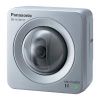
Details zoom, pan/tilt, sensor, illuminance, focus, aperture, and viewing angles.
Lists image compression, resolution, audio, protocols, dimensions, and power.
Describes the CPU, power supplies, clock, bus, memory, and peripheral interfaces.
Details the CCD sensor, analog front end, timing generator, and signal connections.
Explains image capture, scaling, JPEG/MPEG-4 encoding, and video output.
Describes audio signal flow, microphone input, PCM codec, and audio output.
Details the Ethernet MAC, PHY, transformer, and RJ-45 connector for network communication.
Explains the control of pan and tilt motors using GPIO and photo sensors.
Outlines the DC-DC converter circuit and series regulator for power distribution.
Describes Power over Ethernet receiving, PD certification, and voltage drop sections.
Covers I/O terminals, Clear Setting SW, and dual-color LED indicators.
Guides on connecting the camera via PoE or AC adapter, including network setup.
Instructions for initial camera setup, network configuration, and software installation.
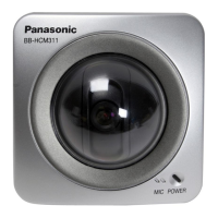
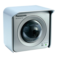
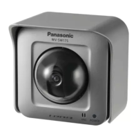
Provides methods and precautions for mounting the camera using different stands or wall mounts.
Flowchart for diagnosing basic operational issues based on indicator lights.
Flowchart for checking PAN, TILT, brightness, white balance, and video output.
Procedure to check power supply voltages and associated components.
Steps to check CPU peripheral block waveforms and identify defective components.
Flowchart for diagnosing issues within the camera image sensor and processing block.
Procedure to check audio input, microphone, PCM codec, and output circuits.
Steps to diagnose problems with the LAN interface, PHY, and connectors.
Flowchart for troubleshooting pan and tilt motor operations and home position detection.
Procedure to check external input/output terminals and associated transistors.
Steps to verify SD card recording functionality and check the interface.
Procedure to check the Real-Time Clock circuit, frequency, and battery backup.
Flowchart for diagnosing LED indicator circuit issues, including voltage and component checks.
Interpreting self-diagnosis results (AA-NN codes) for component checks.
Steps to verify and perform firmware version upgrades through the network interface.
Instructions for resetting camera settings to factory defaults via software or physical button.
Procedure for replacing the MAC address label when replacing the CPU board.
Guide for replacing flat package ICs, including preparation, removal, and installation procedures.
Step-by-step guide for disassembling the camera unit, including CPU, I/O, PoE, FPC, and camera boards.
Procedures and precautions for cleaning the camera unit with a dry cloth.
Schematic diagram for the CPU board (BB-HCM511A), detailing component connections.
Schematic diagram for the CPU board (BB-HCM531A), detailing component connections.
Schematic diagram for the I/O board, showing audio, LED, and sensor interfaces.
Schematic diagram for the PoE board, showing power reception and regulation circuits.
Schematic diagram for the camera board, detailing CCD sensor and image processing circuits.
Component layout view of the CPU board, showing placement of ICs and components.
Component layout view of the I/O board, showing placement of ICs and connectors.
Component layout view of the PoE board, showing placement of power components.
Component layout view of the camera board, showing placement of CCD and image processing components.
Explains schematic diagram conventions, component symbols, and safety notices.
Displays various signal waveforms measured on oscilloscope for troubleshooting.
Provides pinout details and identification for common electronic components.
Shows exploded views of the camera unit with numbered parts and their locations.
Lists the accessories and packing materials included with the camera models.
Comprehensive list of replaceable parts with part numbers, descriptions, and remarks.
| Camera Type | Network Camera |
|---|---|
| Resolution | 640 x 480 pixels |
| Lens | f=3.6 mm, F2.0 |
| Night Vision | No |
| Pan/Tilt | No |
| Zoom | No |
| Frame Rate | Up to 30 fps |
| Audio Compression | G.726 |
| Wireless | No |
| Operating Humidity | 20% to 80% (non-condensing) |
| Image Sensor | 1/4 inch CCD |
| Audio | Two-way audio |
| Network Connectivity | 10BASE-T/100BASE-TX |
| Minimum Illumination | 1 lux |
| Video Compression | MPEG-4, JPEG |
| Protocols | TCP/IP, HTTP, FTP, SMTP, DNS |
| Security | Password protection |
| Operating Temperature | 0°C to 40°C |
| Weight | 450 g |
| Pan Range | Not applicable |
| Tilt Range | Not applicable |