17
BB-HCM511A/BB-HCM531A
4.9. Others
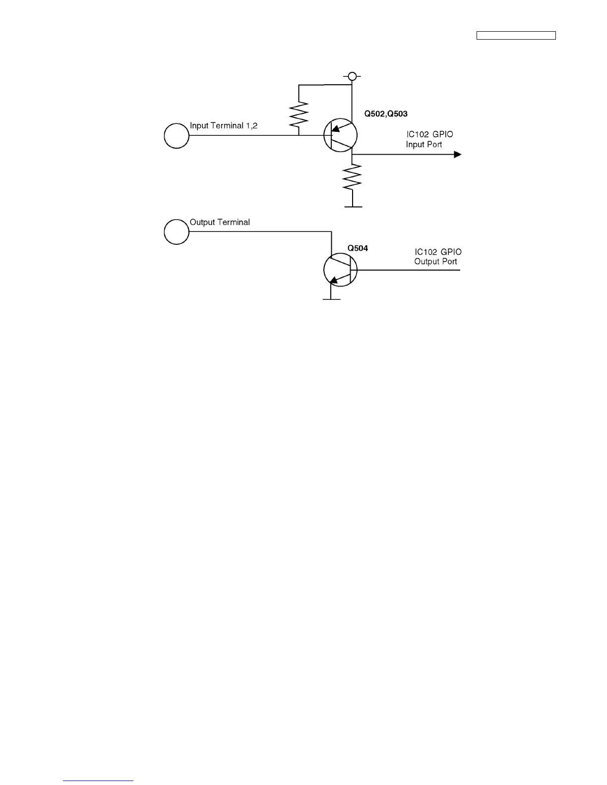
[I/O Terminal]
• The Input terminal has two systems; both of them are connected to the Input Port of the IC102 GPIO.
• Due to Internal Pull-up Resistance, the PNP Transistor (Q502, Q503) on the following level is usually in the OFF state and the
Input Port connected to the collector is at L level.
• If the terminal is short-circuited with the GND or the signal of L level is input, the PNP Transistor goes ON and the Input Port
goes to H level.
• The CPU checks the state of this port regularly to detect a change in this signal.
• The Output terminal is controlled by the Output Port of the IC102. When the Port output is L, the transistor (Q504) on the follow-
ing level is OFF and, when the output is H, the transistor is ON. This transistor has open collector output and it controls external
equipment via external pull-up.
[Clear Setting SW]
• The Clear Setting SW (SW102) is connected to the Input Port of the GPIO. It is usually at H level and goes to L level, when the
SW is pressed.
• The CPU monitors this Input Port periodically and, if it detects that this SW is pressed longer than a specified period, the setting
values other than the RTC are returned to factory settings.
[LED]
• The LED (LED501) has two-color LEDs (red and green). When the transistor (Q505, Q506) connected to each LED is turned
ON/OFF via the Output Port of the IC102, it controls the ON/OFF of the LED.