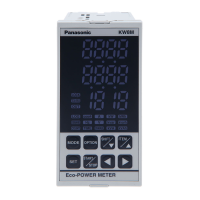
KW8M Eco-POWER METER
4
Chapter 3 Wiring
3.1 Main unit terminal arrangement
Function No. Function
①
⑪
Measured
voltage
input
①
⑪
Power
Supply
L
② ⑫
P0
② ⑫
N ③
⑬
P2
③ ⑬
Pulse
Input
+
④
⑭
④
⑭
-
⑤
⑮ CT1 (+)
Measured
CT
input
⑤ ⑮
Pulse
Output
+
⑥
⑯ CT1 (-) ⑥ ⑯
-
⑦
⑰
+
⑦
⑰
RS485
+
⑧
⑱ CT2 (-) ⑧ ⑱
-
⑨
⑲ CT3 (+) ⑨ ⑲
E ⑩
⑳ CT3 (-) ⑩ ⑳
The input voltage to each terminal is as follows.
Terminal Phase and wire Terminal Input voltage
Single-phase,
two-wire
②-③
-240VAC (100 - 240V~)
(Line voltage)
Measured
voltage input
⑪-⑫
0-440VAC ( 0-440V~)
(Line voltage)
Single-phase,
three-wire
⑪-⑫-⑬
0-220VAC ( 0-220V~:3W)
(Phase voltage)
⑪-⑫-⑬
0-440VAC ( 0-440V 3~)
(Line voltage)
⑪-⑫-⑬-⑭
0-254VAC ( 0-254V 3N~)
(Phase voltage)
Caution for Wiring
1) Terminal fastening torque should be 0.6 to 1.0N・m.
2) This has no built-in power switch, circuit breaker for power supply part. To protect the device, it is
necessary to install power switch and circuit breaker in the power supply circuit.
And this has no built-in power switch, circuit breaker or fuse for measured voltage input parts.
Therefore it is necessary to install them in the circuit near this unit.
3) The terminal block of KW8M is designed to be wired from left. Insert wires to the terminal from the
left and fasten with terminal screws.
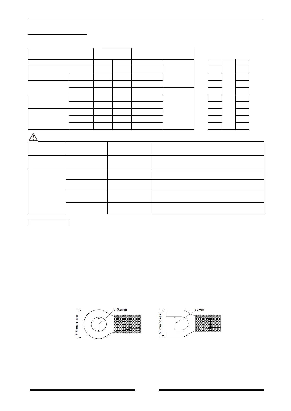
4) In case using insulation sleeve, use an insulation sleeve applicable to M3 screw. Fastening torque
should be 0.6 to 1.0N・m. (Refer to the below.)
5) We recommend a wire with the cross section of 0.75 to 1.25mm
2
for power supply line and measured
voltage input line.
6) Use flame-resistant cable for each wiring.
 Loading...