58
KX-FLB802CX/KX-FLB812CX/KX-FLB802CXS/KX-FLB812CXS
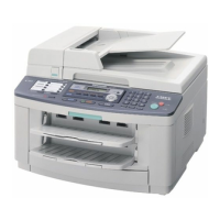
6.13.13. OPTION HANDSET HOOK SWITCH
When the option handset is raised, the switch is turned off, and the signal of IC600-K16pin becomes low level.
When the option handset is settled, the switch is turned on, and the signal of IC600-K16pin becomes high level.
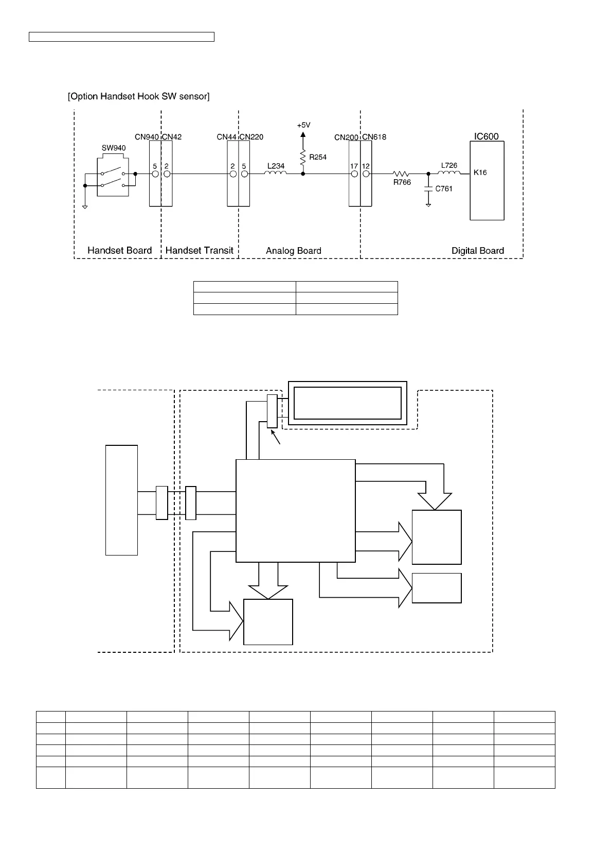
6.14. OPERATION BOARD SECTION
The unit consists of a LCD (Liquid crystal display), KEYs and LEDs (light-emitting diodes). They are controlled by the Gate Array
(IC101) and G/A (IC604: on the DIGITAL BOARD).
The key matrix table is shown below.
1. Key Matrix
a. Hard Scan
*LED7 should be set to KSL4. "8 x 5" key matrix is executed by hardware scanning.
Signal (IC600-K16pin)
ON HOOK High level
OFF HOOK Low level
KIN0 KIN1 KIN2 KIN3 KIN4 KIN5 KIN6 KIN7
KSL0213→ STOP FAX MENU Caller ID
KSL1546↑←HELP Auto Answer
KSL2 8 7 9 SET COPY S1 S6
KSL3 FLASH REDIAL MONITOR ↓ START S2 ZOOM S7
KSL4
(LED7)
0
*
# RESOLUTION SCAN CONTRAST
CN102CN613
IC604
ASIC
LCD MODULE
CN103
8x5
KEYS
MATRIX
(Hard)
LED
DIGITAL BOARD OPERATION BOARD
GATE ARRAY IC
IC101
3x2
KEYS
MATRIX
(Soft)