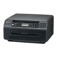
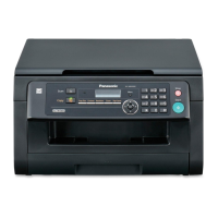
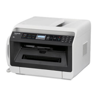
Do you have a question about the Panasonic KX-FLB802CX and is the answer not in the manual?
Provides a detailed connection diagram illustrating the unit's internal circuitry.
Outlines the general block diagram of the unit's ICs and their functions.
Details the facsimile section, including digital, analog, and modem circuit operations.
Describes the modem section's function, transmission time, standards, and communication technology.
Details the engine motor, ADF motor, and FB motor drive circuits and their operations.
Explains the LSU layout, its components, and the laser scanning mechanism.
Provides specifications and diagrams for the high voltage power supply section.
Explains how thermistor and HTRCTL signal control the heat lamp and thermostats.
Provides a block diagram and key components for troubleshooting the power supply board.
Identifies all controls and keys on the unit's control panel.
Covers installation space, document tray, and output tray setup.
Instructions for replacing toner cartridge and drum unit, including cautions.
Lists codes for performing simple checks on unit functions and troubleshooting.
Explains User Mode and Service Mode for programming and lists.
Lists service codes, functions, set values, and remarks for various settings.
Details the specification for clearing memory data for user and service modes.
Lists display messages for user-recoverable errors and their causes/remedies.
Explains how to change parameters remotely using DTMF tones.
Details the procedure for entering remote programming and changing service codes.
Lists user and service functions with their settings, defaults, and remarks.
Explains the approach to troubleshooting, identifying parts, and analyzing problems.
Provides a flowchart for starting the troubleshooting process based on symptoms.
Explains the two types of initialization (short and long) and their functions.
Lists functions to check with corresponding judgments (OK/NG) and references.
Provides guides for printing, paper feed, and copy/fax issues.
Guide for troubleshooting "CALL SERVICE" errors, categorized by service number (1-6).
Troubleshooting guides for ghost images, vertical/horizontal lines, and darkness issues.
Troubleshooting for paper feed issues: multiple feeds, skew, no feed, and jams.
Troubleshooting for ADF issues: document feed, jams, skew, and image quality.
Troubleshooting for defective facsimile transmission and reception.
Troubleshooting steps for initializing errors where the system fails to boot up.
Troubleshooting for operation panel errors like no key input or LCD display.
Guides for troubleshooting various sensors and switches.
Troubleshooting for FB and ADF motor issues.
Troubleshooting flowchart for the LSU section.
Troubleshooting flowchart for the CIS control section.
Procedures for checking high voltage output values at various terminals.
Troubleshooting for Main, CHG/GRID, TRA, DEV DC, DEV AC, and TRA (-) bias.
Troubleshooting steps for USB communication, PC settings, and digital unit confirmation.
Troubleshooting for power supply board issues, including key components and flowcharts.
Instructions for clearing document jams in the ADF.
| Print Technology | Laser |
|---|---|
| Print Resolution | 600 x 600 dpi |
| Paper Capacity | 250 sheets |
| Display | LCD |
| Modem Speed | 33.6 kbps |
| Type | All-in-One Printer |
| Functionality | Print, Copy, Scan, Fax |
| Connectivity | USB |


 Loading...