92
KX-FLB802CX/KX-FLB812CX/KX-FLB802CXS/KX-FLB812CXS
10 Test Mode
10.1. TEST FUNCTIONS
The codes listed below can be used to perform simple checks of some of the unit’s functions. When complaints are received
from customers, they provide an effective tool for identifying the locations and causes of malfunctions.
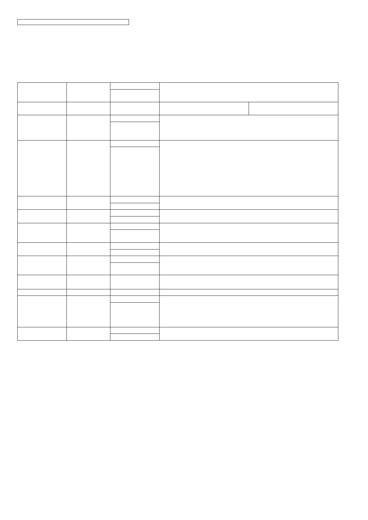
Test Mode Type of Mode Code Function
Operation after code
input
MEMORY CLEAR Service Mode “5” “5” “0” Clear the memory where the users can
store data.
MOTOR TEST &
High Voltage Power
Supply Board
CHECK
Service Mode “5” “5” “6” 0:printer motor feed 4:auto document feed 6:carriage
Refer to HIGH VOLTAGE VALUE CHECK POINT (P.177).
SET
MODEM TEST Service Mode “5” “5” “4” Telephone line circuit is connected automatically, output the following signals on
the circuit line.
1) OFF 2) V21 ter 300bps 3) V27 ter 2400bps 4) V27 ter 4800bps
5) V29 7200 6)V29 9600bps 7) V17 7200bps 8) V17 9600bps
9) V17 12000bps 10) V17 14400bps 11) V34 2400bps 12) V34 4800bps
13)V34 7200bps 14)V24 9600bps 15) V34 12000bps 16) V34 14400bps
17)V34 16800bps 18)V34 19200bps 19) V34 21600bps 20) V34 24000bps
21)V34 26400bps 22)V34 28800bps 23) V34 31200bps 24) V34 33600bps
25)1100Hz 22)2100Hz
SET
ROM CHECK Service Mode “5” “5” “1” Indicates the version and checks the sum of the ROM.
SET
LCD TEST Service Mode “5” “5” “8” Checks the LCD indication.
Illuminates all the dots to check if they are normal.
SET
DTMF SINGLE
TONE TEST
Service Mode “5” “5” “2” Outputs the DTMF as single tones. Used to check the frequencies of the individ-
ual DTMF tones. Refer to DTMF SINGLE TONE TRANSMIT SELECTION (P.94).
1....ON
2....OFF
LED TEST Service Mode “5” “5” “7” All LEDs above the operation panel board flash on and off, or are illuminated.
KEY TEST Service Mode “5” “6” “1” Checks the button operation.
Indicates the button code on the LCD while the button is pressed. Refer to BUT-
TON CODE TABLE (P.94).
START (any key)
SCANNER TEST Service Mode “5” “5” “5”
LED lights up, Scanner scanning.
1:RED / 2:GREEN / 3:BLUE / 4:monochrome / 5:color
LSU TEST Service Mode “6” “3” “9” Laser radiates, Polygon rotates
FAN TEST Service Mode “6” “7” “7” 1:TEST OFF
2:High-speed rotation (Right FAN)
3:Low-speed rotation (Right FAN)
4:High-speed rotation (LEFT FAN )
5:Low-speed rotation (LEFT FAN)
MEMORY CLEAR
(except History data)
Service Mode “7” “1” “0” Refer to Memory Clear Specification (P.99).
SET