2
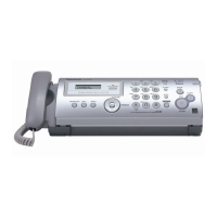
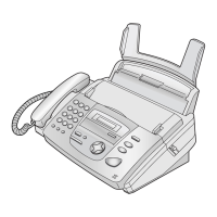
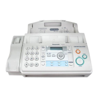
KX-FP215
TABLE OF CONTENTS
PAGE PAGE
1 Safety Precautions -----------------------------------------------5
1.1. For Service Technicians----------------------------------5
1.2. AC Caution---------------------------------------------------5
1.3. Personal Safety Precautions----------------------------6
1.3.1. Moving Sections of the Unit-------------------------6
1.3.2. Live Electrical Sections ------------------------------6
1.4. Service Precautions ---------------------------------------7
1.4.1. Precautions to Prevent Damage from
static Electricity ----------------------------------------7
2Warning--------------------------------------------------------------8
2.1. About Lead Free Solder (PbF: Pb free) --------------8
2.1.1. Suggested PbF Solder-------------------------------8
2.2. Insulation Resistance Test -------------------------------9
2.3. Battery Caution ---------------------------------------------9
2.4. Discarding of P. C. Board --------------------------------9
3 Specifications ----------------------------------------------------10
4 General/Introduction------------------------------------------- 11
4.1. Optional Accessories------------------------------------ 11
5Features------------------------------------------------------------ 11
6 Technical Descriptions---------------------------------------- 12
6.1. Connection Diagram-------------------------------------12
6.2. General Block ---------------------------------------------13
6.2.1. General Block Diagram ----------------------------14
6.3. Control Section ------------------------------------------- 15
6.3.1. Block Diagram----------------------------------------15
6.3.2. Memory Map------------------------------------------16
6.3.3. ASIC (IC501) -----------------------------------------17
6.3.4. Flash Memory (IC506) -----------------------------20
6.3.5. Dynamic RAM (IC503) -----------------------------20
6.3.6. Reset Circuit (Watch dog timer) -----------------21
6.3.7. RTC Backup Circuit---------------------------------22
6.3.8. Supervision Circuit for the Thermal Head
Temperature ------------------------------------------23
6.4. Facsimile Section ----------------------------------------24
6.4.1. Image Data Flow During Facsimile
Operation----------------------------------------------24
6.4.2. Block Diagram----------------------------------------25
6.4.3. Thermal Head ----------------------------------------26
6.4.4. Scanning Block --------------------------------------28
6.4.5. Stepping Motor Drive Circuit----------------------29
6.5. Sensors and Switches ----------------------------------31
6.5.1. Document Top Sensor (SW351)-----------------32
6.5.2. Document Set Sensor (SW352) -----------------32
6.5.3. Paper Top Sensor (SW1001)---------------------33
6.5.4. Cover Open Sensor (SW1001) ------------------33
6.5.5. Film End Sensor (SW1003)-----------------------34
6.5.6. Motor Position Sensor (SW1004) --------------- 34
6.5.7. Hook Switch (SW1501) ----------------------------34
6.6. Modem Section -------------------------------------------35
6.6.1. Function------------------------------------------------ 35
6.6.2. Modem Circuit Operation--------------------------41
6.7. NCU Section-----------------------------------------------42
6.7.1. General------------------------------------------------ 42
6.7.2. EXT. TEL. Line Relay (RLY101)----------------- 42
6.7.3. Bell Detection Circuit------------------------------- 42
6.7.4. Pulse Dial Circuit and ON/OFF Hook
Circuit -------------------------------------------------- 42
6.7.5. Line Amplifier and Side Tone Circuit ----------- 43
6.7.6. Auto Disconnect Circuit --------------------------- 43
6.7.7. Calling Line Identification Circuit---------------- 44
6.8. ITS (Integrated telephone System) and
Monitor Section------------------------------------------- 45
6.8.1. General------------------------------------------------ 45
6.8.2. Speakerphone Circuit------------------------------ 45
6.8.3. Handset Circuit -------------------------------------- 45
6.8.4. Monitor Circuit for Each Signals----------------- 45
6.9. Operation Board Section ------------------------------ 46
6.10. LCD Section----------------------------------------------- 47
6.11. Power Supply Board Section ------------------------- 48
7 Location of Controls and Components ----------------- 51
7.1. Overview--------------------------------------------------- 51
7.2. Control Panel --------------------------------------------- 51
8 Installation Instructions -------------------------------------- 52
8.1. Installation Space---------------------------------------- 52
8.2. Connections----------------------------------------------- 53
8.3. Installing the Ink Film ----------------------------------- 53
8.4. Installing the Paper Tray ------------------------------- 55
8.5. Paper Support -------------------------------------------- 55
8.6. Installing the Recording Paper ----------------------- 56
9 Operating Instructions---------------------------------------- 57
9.1. Setting Your Logo---------------------------------------- 57
10 Test Mode --------------------------------------------------------- 58
10.1. DTMF Signal Tone Transmit Selection------------- 59
10.2. Button Code Table--------------------------------------- 60
10.3. Print Test Pattern ---------------------------------------- 61
11 Service Mode----------------------------------------------------- 62
11.1. Programing and Lists----------------------------------- 62
11.1.1. Operation --------------------------------------------- 62
11.1.2. Operation Flow -------------------------------------- 62
11.1.3. Service Function Table ---------------------------- 63
11.1.4. Memory Clear Specification ---------------------- 65
11.2. The Example of the Printed List --------------------- 66
11.2.1. User Mode-------------------------------------------- 66
11.2.2. Service Mode Settings ---------------------------- 67
11.2.3. History ------------------------------------------------- 68
12 Troubleshooting Guide--------------------------------------- 70
12.1. Troubleshooting Summary ---------------------------- 70
12.1.1. Precautions------------------------------------------- 70
12.2. Error Messages-Display ------------------------------- 71
12.3. Error Messages-Report -------------------------------- 73
12.3.1. Journal Report--------------------------------------- 73
12.3.2. Special Service Journal Report------------------ 82
12.3.3. Communication Section--------------------------- 86
12.4. Remote Programming---------------------------------- 95

 Loading...
