43
KX-FP215
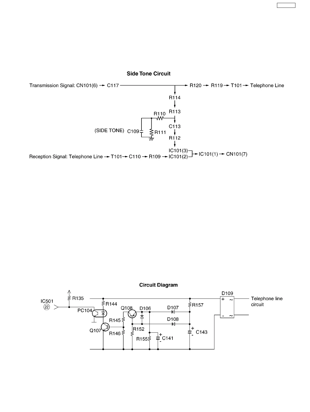
6.7.5. Line Amplifier and Side Tone Circuit
1. Circuit Operation
The reception signal output from the line transformer T101 is input to pin (2) of IC101 via C110 and R109 and then the signal
is amplified at pin (2) of IC101 and sent to the reception system at 0dB.
The transmission signal is output from CN101 (6) and transmitted to T101 via R120 and R119. If the side tone circuit is not
applied, the transmission signal will return to the reception amplifier via C110 and R109. When the side tone circuit is active,
the signal output from IC101 pin (1) passes through R114, R113, C113 and R112 and goes into the amplifier IC101 pin (3).
This circuit is used to cancel the transmission return signal.
6.7.6. Auto Disconnect Circuit
1. Function
This circuit is used to detect that the telephone connected in parallel to the same line is OFF-hook while the unit picks up the
line. If this detection circuit is activated when TAM is being delivered, the delivery stops and the circuit is automatically
released.
2. Circuit Operation
If the line is picked up, C141 is charged by following the path shown below.
D109 (+) → R157 → D107 → C141
When the electric potential difference between the base and emitter of Q108 becomes less than about 0.3V, Q108 and Q107
and PC104 turn off, then the IC501 pin 22 becomes a high level.
In this condition, if a telephone connected in parallel goes into OFF-hook status, the base of Q108 becomes low.
On the other hand, the emitter of Q108 goes down slowly because the capacitor (C141) is charged. Q108 turns on when the
electric
potential difference between the base and emitter of Q108 becomes more than 0.6 V while being charged.
When Q108 turns on, Q107 and PC104 also turn on, then the IC501 pin 22 becomes a low level.
 Loading...