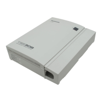
Power Supply Unit Capacity
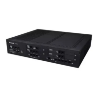
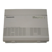
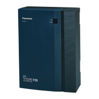
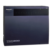
The pre-installed power supply unit (PSU) in each PBX supports a different load figure.
PBX Model Maximum Load Figure
KX-NCP500/KX-NCP1000 44
Load Figure Calculation
Equipment Type Load Figure
PT KX-DT300 series DPT/KX-DT300 series DSS
console/KX-T7600 series DPT/KX-T7600 series
DSS console
1
KX-T7560/KX-T7565 DPT 1
Other DPT/Other DSS console 4
APT 4
IP-PT 0
SIP Extension 0
Extension Card
*1
DHLC4 4
SLC8 8
SLC16 16
PT-interface CS (2-channel) (1 unit) 4
PT-interface CS (8-channel) (1 unit) 8
IP-CS (8-channel) (1 unit) 0
ISDN Extension 2
VPS (1 port) 1
*1
Only the extension cards that can support SLTs count for the load figures.
Notice
If the total
load figure exceeds the maximum load figure of the PBX by 3, the corresponding extension card
cannot be supported by the PBX.
Calculation Example
Lines and Equipment Load Figure
Required Card
Small Free
Slot
Regular
Free Slot
Virtual Slot
Trunk PRI 1 line (23ch) – PRI23 – –
Analogue
Trunk
4 lines – LCOT4 – –
SIP Trunk 4 lines – – – V-SIPGW16
H.323 Trunk 4 lines – – – V-IPGW16
Installation Manual 33
1.3.3 System Capacity

 Loading...


