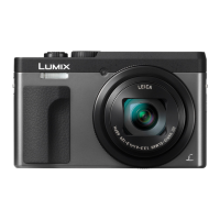
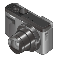
Do you have a question about the Panasonic Lumix DC-TZ90EB and is the answer not in the manual?
General safety guidelines for servicing the equipment, including important notices and precautions.
Procedure to measure resistance between AC plug and exposed metallic parts for safety.
Procedure to measure voltage across a resistor connected to exposed parts for safety.
Step-by-step guide to safely discharge capacitors on the Top P.C.B. unit before servicing.
Techniques to prevent damage to sensitive electronic components from static electricity during servicing.
Information on how to recycle the product's lithium-ion battery, with contact details.
Detailed procedure for safely removing and replacing the device's lithium battery, including cautions.
Overview of the service manual's purpose and how to use it for understanding and servicing the model.
Critical notices regarding specific components like the lens block, Venus Engine, Flash ROM, and cables.
Information about the lens unit, MOS sensor, and optical tilt adjustment procedures.
Details about the Venus Engine chip, its package type, and servicing precautions.
Procedure for adjusting firmware after replacing Flash ROM or Charging Control Microcomputer.
Precautions for handling flexible cables and connectors to prevent damage or contamination.
Notes related to Wi-Fi function and important servicing notices concerning customer data.
Description of the camera's Wi-Fi features and operations, with page references.
Instructions on erasing customer personal information before returning the camera after repair.
Information on the use of lead-free solder in the equipment and service cautions.
Method to identify model suffixes (NTSC/PAL) based on safety registration marks on the nameplate.
Procedure for performing initial settings after replacing major components like the Main P.C.B. or Flash-ROM.
Description of the error code memory function and how to display recorded error codes.
Detailed list of error codes, their meanings, detecting devices, and corresponding parts/circuits.
Troubleshooting steps for Wi-Fi function issues and procedures for password removal.
Steps to reset Wi-Fi settings and remove password protection for servicing.
Procedure to confirm Wi-Fi circuit functionality by checking wireless access point display.
List and images of service fixtures and tools required for checking and servicing the unit.
Important note about performing adjustments after replacing the Main P.C.B.
Description of the service position and required extension cables for checking and replacing parts.
Diagram showing the connections of extension cables for servicing specific units.
A flowchart illustrating the sequence of disassembly for the camera unit.
Diagram showing the location of various Printed Circuit Boards (PCBs) within the camera.
Detailed step-by-step procedures for disassembling the camera unit and its components.
Step-by-step instructions and diagrams for removing the rear case unit, including the LCD.
Procedure for removing the rear operation P.C.B. unit, including flex cable handling.
Instructions for removing the frame plate, involving hinge cover and LCD unit.
Steps for removing the main P.C.B. and speaker, including flex cable and heat radiation pad handling.
Procedure for removing the eye sensor FPC, with notes on handling and attaching the eye sensor sheet.
Steps for removing the lens unit, including heat radiation sheet removal and attachment notes.
Instructions for removing the top case unit, including locking tabs and screw locations.
Procedure for removing the LVF unit, Top P.C.B., and Flash unit, with parts list and handling notes.
Steps for removing the PCB spacer, front case unit, and control ring unit.
Instructions for removing the battery door unit, including spring and shaft components.
Procedure for removing the right strap cover, strap plate, and front earth plate.
Instructions for removing the left battery P.C.B., strap cover, and strap plate.
Procedure for removing the battery case, with notes on gasket attachment.
Steps for removing the LCD unit, including hinge cover and rear case unit.
Precautions and step-by-step procedures for disassembling the camera's lens unit.
Detailed steps for removing the master flange unit, including screws, solder points, and flex units.
Procedure for removing lens frame units, involving relay gear and fix frame unit.
Instructions for removing the 1st and 3rd lens frame units from the cam frame unit.
Procedure for removing the 2nd lens frame unit from the cam frame unit.
Procedures for assembling the lens unit, including inserting various lens frame units.
Step-by-step guide for inserting the 2nd lens frame unit, aligning parts and pins.
Procedure for inserting the 1st lens frame unit, aligning printing portions and cam pins.
Instructions for inserting the 3rd lens frame unit, aligning metal parts and cam pins.
Procedure for inserting the fix frame unit, aligning zoom motor and cam pins.
Steps for inserting the master flange unit, aligning shutter FPC and positioning bosses.
Procedure for removing the MOS unit, including Torx screws, tilt springs, and optical tilt adjustment requirements.
Overview of the importance of performing adjustments after part replacements and troubleshooting.
Notes on initial settings release and procedures for releasing camera initial settings.
Steps to release camera initial settings, which is necessary before automatic alignment software execution.
Recommended procedure for backing up Flash-ROM data before disassembling the unit.
Instructions on removing the front hood of the light box for optimal adjustment setup.
Comprehensive guide on executing electrical adjustments, including startup, flag setting, and execution steps.
Detailed steps for entering service mode, setting flags, and performing electrical adjustments.
Procedure to enter the service mode for electrical adjustments.
Instructions on resetting and checking the status flag conditions for adjustments.
Steps to perform adjustments, including resetting flags and pressing the shutter button.
Important points to consider during adjustment, such as not moving the equipment or pressing buttons.
Steps for finalizing adjustments, including cancelling the mode and confirming completion.
A matrix table detailing adjustments required for replaced parts, including required jigs and operating procedures.
Guidelines for cleaning the lens, viewfinder, and LCD panel using appropriate tools and methods.
A high-level block diagram illustrating the main functional units and their interconnections.
Detailed block diagram showing the system control logic and connections between PCBs.
Block diagram illustrating the audio, video processing, and HDMI interface pathways.
Block diagram showing the functional blocks related to the lens unit and flash system.
Block diagram illustrating the power supply circuits, including battery and USB power management.
Block diagram detailing the power regulation circuits and voltage distribution within the device.
Schematic diagram showing the interconnection of various units and PCBs within the camera.
| Sensor Type | MOS |
|---|---|
| Megapixels | 20.3 |
| Optical Zoom | 30x |
| Lens | Leica DC VARIO-ELMAR |
| ISO Range | 80 - 6400 |
| Touch Screen | Yes |
| Video Recording | Yes |
| Built-in Flash | Yes |
| Wi-Fi | Yes |
| NFC | Yes |
| GPS | No |
| Digital Zoom | 4x |
| Shutter Speed | 1/2000 - 60 sec |
| Continuous Shooting Speed | 10 fps |
| Focal Length | 4.3 - 129mm |
| Maximum Aperture | f/3.3 - f/6.4 |
| ISO Sensitivity | Auto, 80 |
| Extended ISO Mode | Yes |
| LCD Screen Size | 3.0 inches |
| LCD Screen Resolution | 1, 040, 000 dots |
| Viewfinder | Electronic (1, 166, 000 dots) |
| Video Resolution | 4K (3840 x 2160) |
| Battery Life | Approx. 380 shots |
| Connectivity | USB 2.0, HDMI micro |
| Image Stabilization | 5-axis Hybrid O.I.S. |
| Battery | Li-ion Battery Pack (3.6V, 1025mAh, 3.7Wh) |
| Weight | Approx. 322g with battery and SD Memory Card |


 Loading...